Hack the Digispark BlinkStick and ATtiny85 Microcontroller into a FadeStick
Background
The BlinkStick device came from Kickstarter as an RGB LED connected to a USB port to signal some notification like a new email. With an API you can send it commands to change the LED color and make it, well, blink. The hardware is based off the ATtiny85 8-pin, 8KB AVR microcontroller. Later a company called DigiStump made a similar-but-LEDless USB dongle called Digispark for Arduino development using the same ATtiny85. It was found that by soldering an LED and with some tweaks1 the open-source BlinkStick firmware will run on the Digispark USB development board.
Six years have gone by and the BlinkStick Github repo has gone dormant. The API code repo has also gone cold with only a smattering of forks.
Motivation
My compute cluster has 28 CPUs and each has a USB slot for a status LED. I’m currently using the stock BlinkStick firmware and Digispark clones2.
The problem is that the host CPU must manage the timing and duration of the colors for interesting and colorful patterns. This means my compute cluster is spending many CPU cycles on just looking pretty. My goal is to hack the abandoned firmware to add a mechanism to upload a color pattern so the microcontroller, not the host CPU, executes the color pattern and timings. Let’s push it to its limits.
Hardware
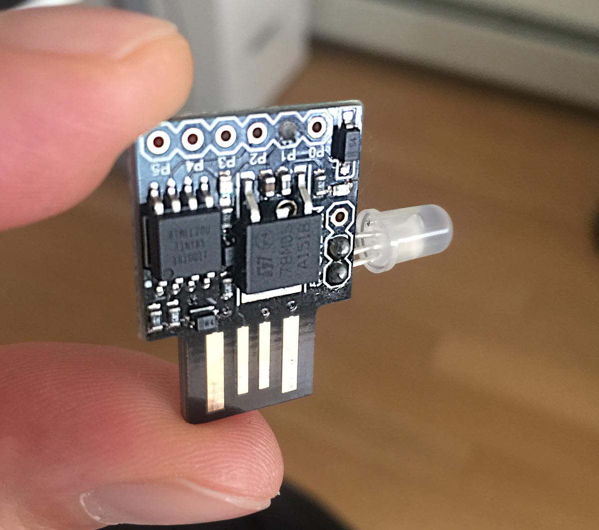
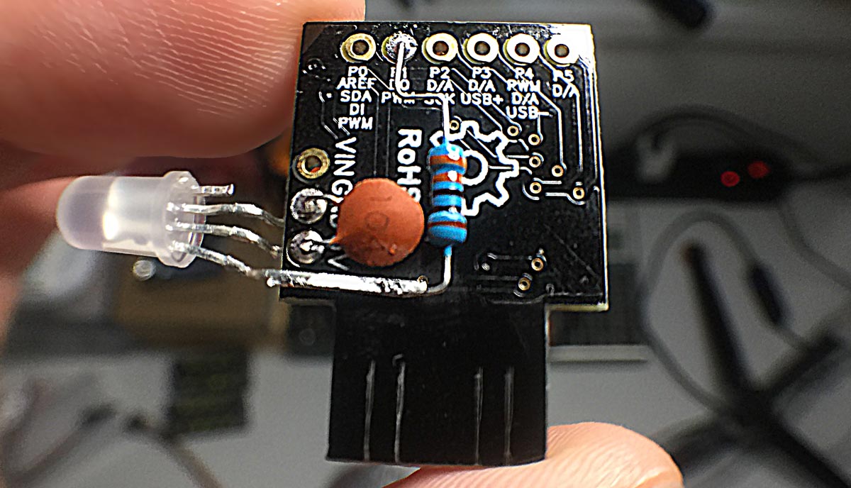
The very first hack is to disable the red power light on the Digispark board. This is an in-circuit light and cannot be disabled with software, but a scalpel does the trick.

I tested both the APA106 and WS2811 LEDs and the APA106 LEDs were superior in brightness, step, and diffusion. Here is an example distinction between the two at the same brightness.

The completed device looks like this prototype:
Software progress
To be honest, I failed in my first 23 attempts to hack the C firmware. I didn’t know anything about interrupt vectors, maintaining registers, and how to deal with 8 bits of data transfer at a time – Java has spoiled me so much. Plus, I have no idea how to debug or trace the microcontroller execution, just trial, error, and patience. I encountered race conditions, lock-ups, and many times the computer wouldn’t recognize my Digispark. I was trying to do something new with this firmware so of course it was tedious and fraught with frustration.
Eventually, I figured out how to create a mutex in the microcontroller world, and came up with a strategy to keep the I/O responsive while the color pattern is executing, as well as upload said color pattern. My hope is that these improvements will be useful to others who want to do neat things with the Digispark and BlinkStick firmware.
Github project repos
- BlinkStick Digispark firmware – Includes a compiled hex file
- BlinkStick Java API – Includes many interesting demos
- Micronucleus Bootloader for APA106 – Special fork for the APA106 LED
How it works
A pattern of up to 62 colors and delays can now be uploaded in a single request. In one API call you can flash the LED red a couple of times with the following byte array payload:
1 | [20, 4, 255, 0, 0, 2, 0, 0, 0, 2, 255, 0, 0, 2, 0, 0, 0, 0] |
To make more sense, let’s group the bytes like so:
1 | [20, 4, (255, 0, 0), 2, (0, 0, 0), 2, (255, 0, 0), 2, (0, 0, 0), 0] |
Even more clearly:
1 | [some id, expect 4 colors, (red), 20 ms, (off), 20 ms, (red), 20 ms, (off), forever] |
You may be wondering how “2” signifies a “20 ms” delay. That is because the range of a byte is 0-255, so I made a judgment call to multiply that by 10 in the backend. That means a delay between 0 and 2.5 seconds is possible per color with a resolution of 10 ms. Also, the 62-color limit is due to a 254-byte v-USB transfer limit. Additional routines could be added to extend this limit, but this is good enough!
Main loop
Essentially the main loop iterates over the color pattern buffer to set a color then waits for some delay and continues.
1 2 3 4 5 6 7 8 9 10 11 12 13 14 15 16 17 18 19 20 21 22 23 24 25 26 27 28 29 30 31 32 33 34 35 | ... /* Main event loop */ for(;;){ usbPoll(); // Process any color patterns if(isBusy) { for ( uint8_t currPatternIndex = 0; currPatternIndex < patternCount; currPatternIndex++ ) { led[0] = patternBuffer[ 2 + (4 * currPatternIndex) + 0 ]; led[1] = patternBuffer[ 2 + (4 * currPatternIndex) + 1 ]; led[2] = patternBuffer[ 2 + (4 * currPatternIndex) + 2 ]; uint8_t delay = patternBuffer[ 2 + (4 * currPatternIndex) + 3 ] * 10; // Restore the delay resolution // Set the LED color ws2812_sendarray_mask(&led[0], 3, _BV(ws2812_pin)); if (delay > 0) delayMs(delay); // This will also call usbPoll() repeatedly for responsive I/O } resetTransfer(); // Reset the patternCount and volatile busy flag } ... } /* Simple non-blocking, responsive delay */ void delayMs(unsigned ms) { for ( unsigned i = 0; /* requires at least C99 */ i < ms; i++) { _delay_ms(1); usbPoll(); } } |
Operation
If the Digispark is idle, it will accept a color pattern to upload and execute it immediately. If it is executing a color pattern, it will accept but ignore any new color patterns until it is idle again. This way the I/O never blocks the host CPU. A color inspection can also be performed anytime meaning the host can query the current color even during a color pattern execution.
Also, the Digispark will turn off the led after 60 seconds of inactivity. The reason is that if the status LED is on and green, then the host goes away, the green status LED will be misleading. I want my LEDs off when the host is idle or shutdown.
Upload
The firmware works best with newer Micronucleus v2.04. Download the main.hex binary from my repo or compile it with make. Then, upload it to the Digistump with:
1 | micronucleus -cdigispark -timeout 60 main.hex |
Brownout-detect (reset) circuit
It turns out that an under-voltage will damage the EEPROMs of the ATtiny85 chips. For example, if the power supply is switched off but it takes a long time for the capacitors to bleed, then the voltage decay will be a gradual descent from 5V to near 0V. During that time the MCU will behave in unexpected ways. For example, here is a snapshot of an EEPROM dump after such an event:
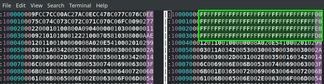
This is the power supply voltage decay after being shut off that caused the EEPROM damage:
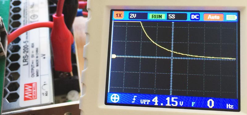
The solution for this problem is to enable the BOD (brownout detect) circuit which is disabled by default. When enabled, under-voltage causes the MCU to reset so it doesn’t run amok on the insufficient voltage. To enable the BOD, the high fuse can be set to 0xDD to activate the BOD threshold to 2.7V.
Results
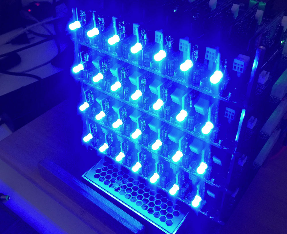
Application
With twenty-eight of these FadeSticks, I can monitor the system resource usage of the processors in my prototype compute cluster.
Notes: