Clusterboard A64 Insidious Reset Problem: Solved
A bare-metal compute node may soft-lock, spin-lock, deadlock, overheat, encounter resource starvation, the Docker daemon goes away, systemd becomes unstable, and on. In these cases, a watchdog timer acting like a dead man’s switch is not updated (pressed), a timer reaches zero, and the promise is the watchdog circuit restarts all the hardware like a power-on reset (POR).
My experience is that I can not get this working out of the box in U-Boot mainline for the Allwinner A64 SoC (sun50i) on a Pine64/SOPINE module in the clusterboard. This problem is more complex than I thought, so if it helps anyone else, I’ll document my thought process and investigation into how I made this work.
Results
- 2xAA RTC batteries in the clusterboard allow a reset.
- 2xAA RTC batteries in the powered clusterboard will die within a few months.
- Back-EMF from the clusterboard’s reset distributor ironically prevents a WDT reset.
- A barrier diode connected to clusterboard D1 and +RTC allows a WDT reset (see solution).
Investigation
Here is everything I’ve tried and my thought process while investigating this non-restart issue.
This is my investigation into solving a problem that has been unsolved for years. Here are the questions I’ve asked myself.
No. The CPU cores may be locked up, or have wrong clock signals, and cannot reach a jump to, say, location zero for the CPU to act as if it were just turned on. We’ll need a hardware solution to reset compute modules – a watchdog timer.
Yes and no. The Allwinner A64 SoC used in the SOPINE (Pine64) modules has a hardware watchdog timer in the processor (A64 PDF schematic, p161), but there is no dedicated watchdog circuit external to the proccessor (SOPINE PDF schematic).
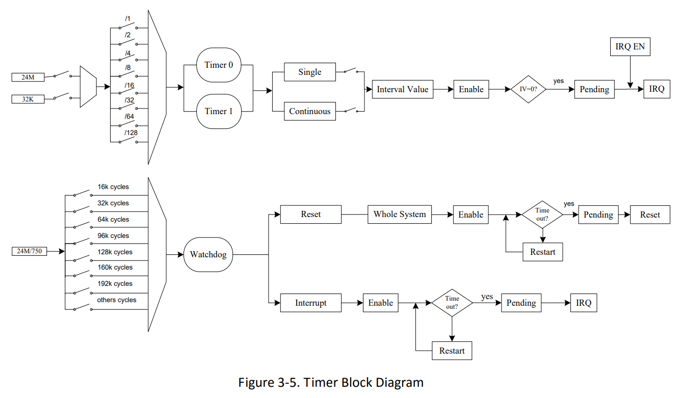
From the previous diagram, the WDT can send an interrupt (IRQ) or a reset signal (but what does “reset signal” mean?).
Useful information from the Allwinner A64 docs:
- Timer register base address:
0x01C20C00, offsets in brackets below. WDOG_IRQ_EN_REG (0xA0)–WDOG_IRQ_ENdefaults to 0, no IRQs are sent.WDOG_CFG_REG (0xB4)–WDOG_CONFIGdefaults to 1 and sends reset signals to the whole system.WDOG_CTRL_REG (0xB0)– SetWDOG_KEY_FIELDto 0xA57 andWDOG_RSTARTto 1 to trigger a reset.WDOG_MODE_REG (0xB8)– SetWDOG_INTV_VALUEto 2 for 2s andWDOG_ENto 1 to enable WDT.
1 2 3 4 5 6 | writel(0x1, WDOG_CFG_REG); // Signal the whole system writel(0x10, WDOG_MODE_REG); // Watchdog interval is 1s writel(readl(WDOG_MODE_REG)|(1<<0), WDOG_MODE_REG); // Enable Watchdog delay_ms(500); writel(readl(WDOG_CTRL_REG)|(0xA57<<1)|(1<<0), WDOG_CTRL_REG); // Writel 0xA57 and 0x1 // The system will reset |
The WDT in the A64 has a countdown register with a maximum 16-second watchdog period. When zero is reached, it generates a system-wide “general reset”.
From the Allwinner A64 docs, the USB controller accepts a reset signal as a register flag to enter USB suspension. The Audio Controller (OWA) accepts a register flag to reset that controller. Even the unused Smart Card Reader (SCR) accepts a reset register flag. The CPU has a few reset registers as well. So, setting a bit in various registers around the SoC causes resets in those associated controllers.
More on the CPU reset, it includes core reset, power-on reset, and H_Reset. The last mode will reset the cluster of cores, i.e. all the cores.
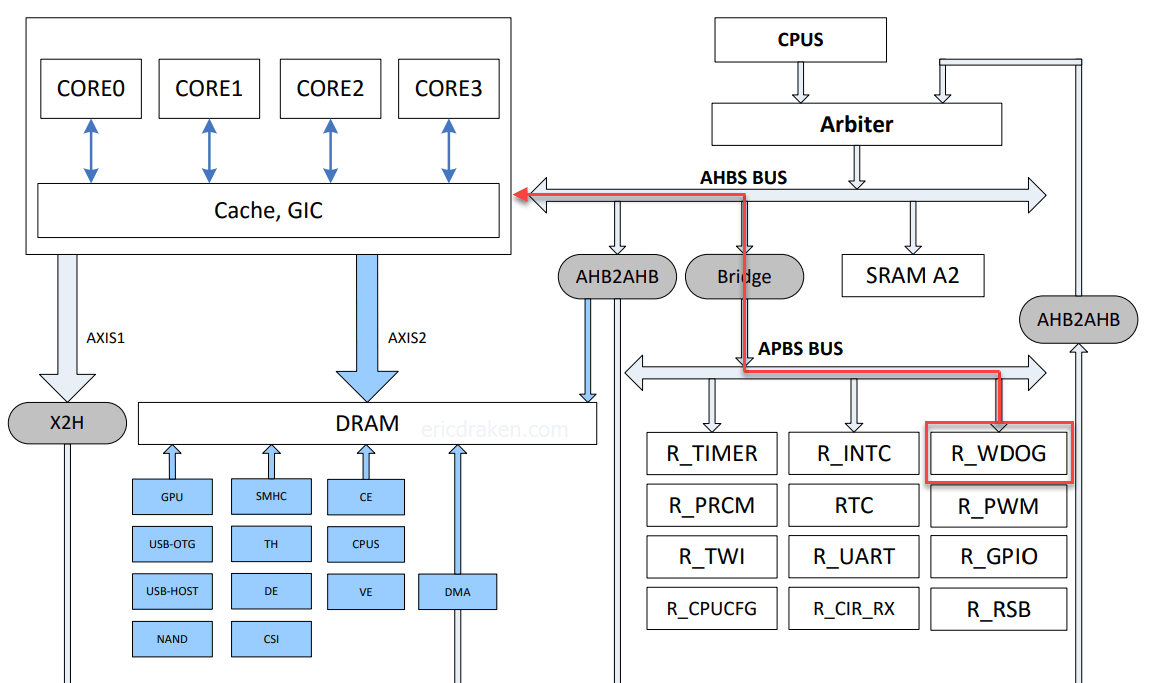
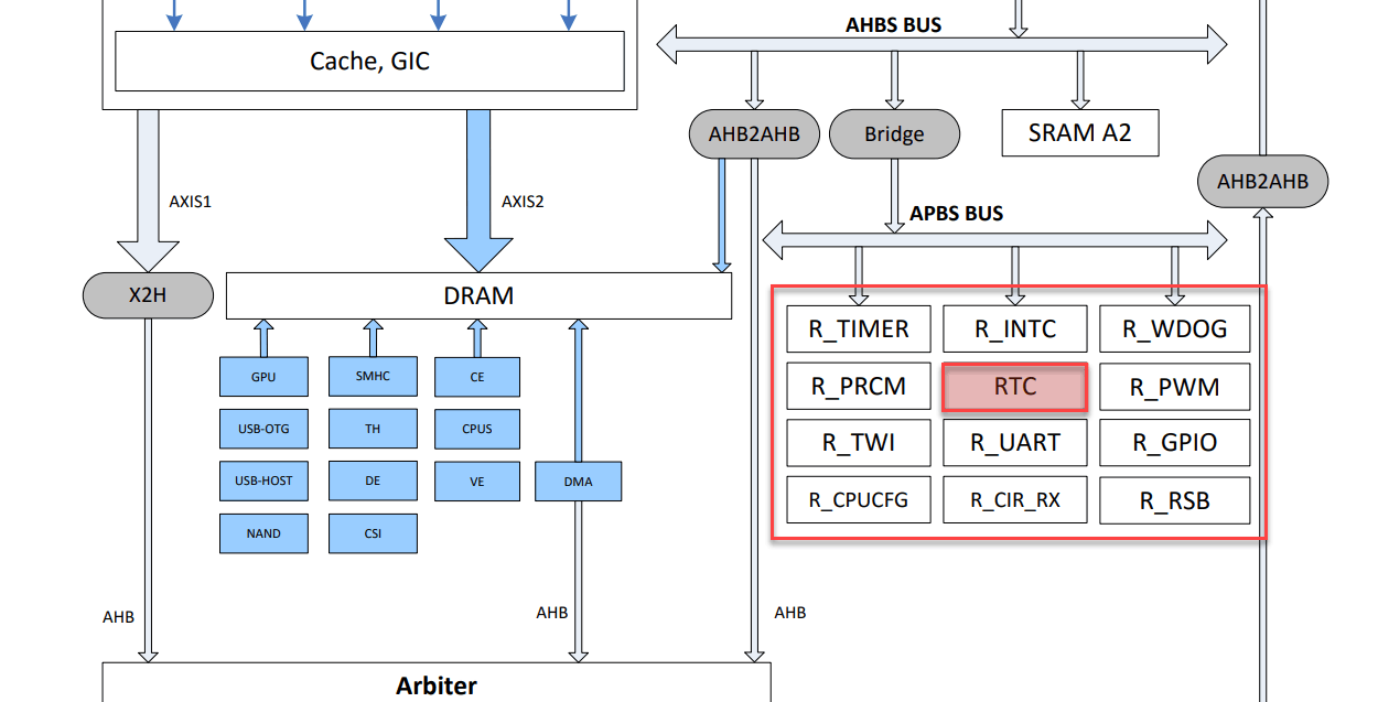
So how do these various reset registers get set? After all, the CPU has gone awry so it cannot set those registers. Let’s look at the A64 bus diagram.
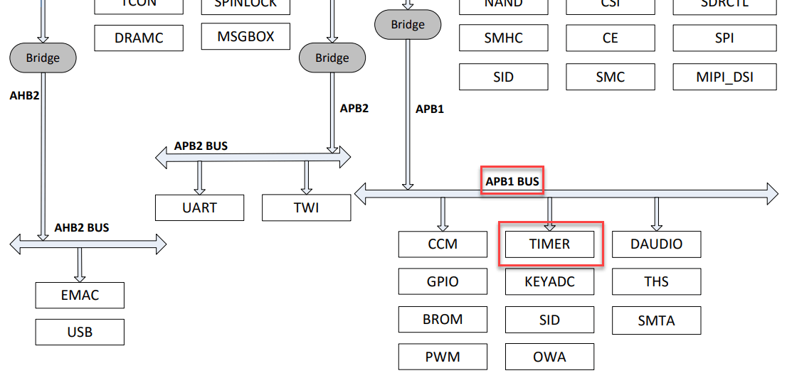
There is something called an Advanced Peripheral Bus (APB) connected to the WDT (timer), which is connected to similar buses.
APB is designed for low bandwidth control accesses, for example, register interfaces on system peripherals. This bus has an address and data phase similar to Advanced High-performance Bus (AHB), but a much reduced, low complexity signal list (for example no bursts). APB is part of Advanced Microcontroller Bus Architecture (AMBA) products licensable from ARM Limited.
From the system diagram above, we see the WDT (timer) puts addresses and data on the APB which crosses a bridge to the AHBs and sets registers in the various controllers – and reset registers are set around the SoC. Now I understand how the WDT resets all peripherals with dedicated buses.
There is an AXP803 Power Management IC (PMIC) external to the A64 SoC that has the ability to vary its voltages programmatically. It’s the power rails for the SoC and peripherals. Can this be programmed to power cycle the SoC?
By physically grounding the PWROK line, the PMIC shuts off. When the grounding is removed, the PMIC comes back to life as if the device were just plugged in. Then, what toggles the PWROK line if the CPU loses power?
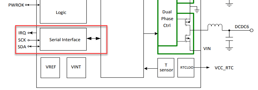
There is a serial interface. What can this do for us? Short answer: nothing. This is a blind alley. The AXP803 is primarily a Li-ion charging IC and does not have any mode like “shut off and then promise to turn back on”. Some external hardware or at minimum an RC (resistor-capacitor) circuit would be needed to achieve a PMIC reset with the SOPINE’s AXP803 PMIC. Let’s stick with the WDT solution.
The AXP803 PMIC monitors such situations as low power, bad battery, PWRON pin signal, over-temperature, and GPIO input edge signals. When the events occur, the corresponding IRQ status will be set to 1 and will drive the IRQ pin low. It’s up to the host to consume/notice this IRQ. When voltage does drop, the PMIC will lower current until the primary voltage rises.
The AXP803 communicates with the A64 via the Reduced Serial Bus (RSB) and thus the A64 can “notice” incoming power error states. That is a rabbit hole I’ll leave, but to answer this line of thinking, yes, there is action taken on brown-out situations.
This is where things go off the rails. There are several community patches/hacks to add support for the AXP803 PMIC, adding a sunxi WDT reset via writing directly to registers, and enabling Driver Model (DM) reset classes. Merely experimenting with PSCI, RESET, SYSRESET, and DM_RESET in U-Boot leads to compiler errors like “Error: do_reset() is already defined”, or runtime errors like “System reset not supported on this platform”, or even the board just hangs. What are the main options?
PSCI
Power State Coordination Interface (PSCI) is used for CPU and overall system power management used for system shutdown and reset. When CONFIG_PSCI_RESET is enabled, on reset, some instruction is written to the PSCI subsystem at an address through the PSCI 0.2 interface when CONFIG_ARM_PSCI_FW is also enabled. Seems simple, and seems complicated. Overwhelmingly, most ARM boards have # CONFIG_PSCI is not set in their defconfigs.
SYSRESET
The vast majority of ARM boards have CONFIG_SYSRESET=y in their defconfigs. This seems to be a modular way to reset various components on the SoC programmatically. It has provisions for warm and cold resets, as well as resetting the PMIC (power off then on according to sysreset.h).
SYSRESET_PSCI
To murky the waters, inside SYSRESET it can interact with PSCI to do the same as PSCI when CONFIG_SYSRESET_PSCI is enabled, but very, very few defconfigs have this.
SYSRESET_WATCHDOG and SYSRESET_RESETCTL
You can see this is getting confusing. This is where I get off this train and experiment with registers, myself.
Having failed to find the right combination of configuration flags over and over again, my new approach is to cause the WDT to fire via a timeout, and eventually via the reset command in the U-Boot shell. My goal is to get the manufacturer’s sample reset code to execute and observe a proper reset by monitoring the A64 via the serial cable.
After disabling PSCI reset with # CONFIG_PSCI_RESET is not set in the defconfig file, let’s examine arch/arm/mach-sunxi/board.c. It has a section with writel instructions from 0x01c20c00. The addressing and bit-twiddling seem fine, actually. When I explicitly try to invoke a sequence of register writes, either nothing happens, or the system hangs when an mdelay() statement is reached, or the board just halts.
Here again is the manufacture’s recommendation.
1 2 3 4 5 6 | writel(0x1, WDOG_CFG_REG); // Signal the whole system writel(0x10, WDOG_MODE_REG); // Watchdog interval is 1s writel(readl(WDOG_MODE_REG)|(1<<0), WDOG_MODE_REG); // Enable Watchdog delay_ms(500); writel(readl(WDOG_CTRL_REG)|(0xA57<<1)|(1<<0), WDOG_CTRL_REG); // Writel 0xA57 and 0x1 // The system will reset |
Being absolutely explicit with my hex values, here is what I tried in code. This loops forever.
1 2 3 4 5 6 7 8 9 10 11 12 13 14 15 16 17 18 | // arch/arm/lib/reset.c #define TIMER_REG 0x01C20C00 // ... snip ... do { putc('A'); writel(0x1, TIMER_REG + 0xB4); // Set 1:0 to 01 putc('B'); // writel((1 << 5), TIMER_REG + 0xB8); // Set 7:4 to 0001 (...00010000) writel(0x10, TIMER_REG + 0xB8); // 0b10000 = 0x10, or 1s putc('C'); writel(readl(TIMER_REG + 0xB8) | (1 << 0), TIMER_REG + 0xB8); // Set 0 to 1 to enable WDT putc('D'); mdelay(500); putc('E'); writel(readl(TIMER_REG + 0xB0) | (0xA57 << 1) | (1 << 0), TIMER_REG + 0xB0); // Set 12:1 as 0xA57, and 0 to 1 // Could also be writel(0x14AF, TIMER_REG + 0xB0); putc('F'); } while(1); |
1 2 3 4 5 | U-Boot> reset ABCDEFABCDEFABCDEFABCDEFABCDEFABCDEFABCDEFABCDEFABCDEFABCDEFABCDEFABCDEFABCDEFABCDEFAB CDEFABCDEFABCDEFABCDEFABCDEFABCDEFABCDEFABCDEFABCDEFABCDEFABCDEFABCDEFABCDEFABCDEFABCD EFABCDEFABCDEFABCDEFABCDEFABCDEFABCDEFABCDEFABCDEFABCDEFABCDEFABCDEFABCDEFABCDEFABCDEF ABCDEFABCDEFABCDEFABCDEFABCDEFABCDEFABCDEFABCDEFABCDEFABCDEFABCDEFABCDEFABCDEFABCDEFAB... |
Frustrating.
My initial search for “Pine64 reset” led nowhere (too specific). There are a handful of unanswered pleas for help in the forums, which is why I tried to debug U-Boot on my own.
One day whilst reaching my wit’s end, I instead searched for “A64 watchdog reset” which led me to a deep thread with brilliant people collaborating in the thread titled “H6 Famous Reboot Problem” with nine pages. Allwinner makes the A64 and H6, the latter being very similar to the A64, but with better video support (not needed in a cluster computer). Jackpot.
People even describe the same path I took:
“I’ve tried to debug the reset_cpu() in arch/arm/mach-sunxi/board.c where it set some Watchdog register and loop infinitely, but it seems that watchdog never kicks in.” (ref)
There was a false victory.
“Bingo! The missing thing is CONFIG_NR_DRAM_BANKS=1.”
Could a certain flag not be set?
“Maybe nowayout param should be set to 1? I remember that nowayout=0 on H3 just disables watchdog hardware reset.”
The next idea was looking at the Arm Trusted Firmware (now called Trusted Firmware A, or TF-A).
“Mainline u-boot has a reset command, which triggers a watchdog-based reboot, and it just locks up the machine, when the watchdog timeout expires. The same thing simply happens in the kernel. The kernel tells ATF to reset, ATF does the same thing as u-boot (watchdog-based reset), and the SoC locks up.” (ref)
A sign of hope emerges.
“Changing to R_WDOG instead of WDOG in ATF fixes the issue. … A patch can be added to
build/patch/atf/atf-sunxi64/.” (ref)
A consensus emerges that the problem is in the ATF (now called TF-A), and the fix (for H6) is as simple as:
1 2 3 4 5 6 7 8 9 10 11 12 13 | diff --git a/plat/allwinner/sun50i_h6/include/sunxi_mmap.h b/plat/allwinner/sun50i_h6/include/sunxi_mmap.h index f36491a8..f01745a4 100644 --- a/plat/allwinner/sun50i_h6/include/sunxi_mmap.h +++ b/plat/allwinner/sun50i_h6/include/sunxi_mmap.h @@ -58,4 +58,7 @@ #define SUNXI_R_UART_BASE 0x07080000 #define SUNXI_R_PIO_BASE 0x07022000 +#undef SUNXI_WDOG_BASE +#define SUNXI_WDOG_BASE SUNXI_R_WDOG_BASE + #endif /* SUNXI_MMAP_H */ -- |
We’re talking about the trusted watchdog now. Could the solution be as simple as pointing the regular watchdog code to the trusted watchdog? Let’s look at the system bus again.
It seems that in 2021 TF-A is already using the secure watchdog (SUNXI_R_WDOG) as we can see below. There is nothing to do here for the A64.
1 2 3 4 5 6 7 8 9 10 11 12 13 14 15 16 17 18 19 | // plat/allwinner/common/sunxi_native_pm.c #define SUNXI_WDOG0_CTRL_REG (SUNXI_R_WDOG_BASE + 0x0010) #define SUNXI_WDOG0_CFG_REG (SUNXI_R_WDOG_BASE + 0x0014) #define SUNXI_WDOG0_MODE_REG (SUNXI_R_WDOG_BASE + 0x0018) // FYI: #define __dead2 __attribute__((__noreturn__)) static void __dead2 sunxi_system_reset(void) { gicv2_cpuif_disable(); /* Reset the whole system when the watchdog times out */ mmio_write_32(SUNXI_WDOG0_CFG_REG, 1); /* Enable the watchdog with the shortest timeout (0.5 seconds) */ mmio_write_32(SUNXI_WDOG0_MODE_REG, (0 << 4) | 1); /* Wait for twice the watchdog timeout before panicking */ mdelay(1000); ERROR("PSCI: System reset failed\n"); panic(); } |
Since the ARM trusted watchdog is, well, trusted (right?), there needs to be communication from user-world to secure-world through the TF-A. Now, the TF-A has the sunxi_system_reset() defined in both sunxi_native_pm.c and sunxi_scpi_pm.c.
1 2 3 4 5 6 7 8 9 10 11 12 13 | // plat/allwinner/common/sunxi_scpi_pm.c static void __dead2 sunxi_system_reset(void) { uint32_t ret; gicv2_cpuif_disable(); /* Send the system reset request to the SCP. */ ret = scpi_sys_power_state(scpi_system_reboot); if (ret != SCP_OK) { ERROR("PSCI: SCPI %s failed: %d\n", "reboot", ret); } psci_power_down_wfi(); } |
We now have to go even deeper to the SCPI, which stands for System Control and Power Interface. Which of the two implementations is used? According to the logic in allwinner-common.mk, the native implementation is used by default. So, how to call this programmatically?
Let’s chase down the “native PSCI ops” structure in sunxi_native_pm.c and see who executes the operation “system_reset”. This led to psci_system_off.c with a method called psci_system_reset(void).
1 2 3 4 5 6 7 8 9 10 11 12 13 14 15 16 | // lib/psci/psci_system_off.c void __dead2 psci_system_reset(void) { psci_print_power_domain_map(); /* Notify the Secure Payload Dispatcher */ if ((psci_spd_pm != NULL) && (psci_spd_pm->svc_system_reset != NULL)) { psci_spd_pm->svc_system_reset(); } console_flush(); /* Call the platform specific hook */ psci_plat_pm_ops->system_reset(); /* This function does not return. We should never get here */ } |
Okay, going deeper, who calls psci_system_reset() then?
1 2 3 4 5 6 7 8 9 10 11 12 13 14 15 | // lib/psci/psci_main.c /******************************************************************************* * PSCI top level handler for servicing SMCs. ******************************************************************************/ u_register_t psci_smc_handler(uint32_t smc_fid, // ... snip ... case PSCI_SYSTEM_OFF: psci_system_off(); /* We should never return from psci_system_off() */ break; case PSCI_SYSTEM_RESET: psci_system_reset(); /* We should never return from psci_system_reset() */ break; |
Sigh. What’s an SMC?
The SMC is an Advanced Microcontroller Bus Architecture (AMBA) compliant SoC peripheral. It is an address-space controller with on-chip AMBA bus interfaces. The user guide gets wordy, but let’s say it’s a gatekeeper to protected address space that the TF-A secure code uses.
Back to U-Boot, we see that in the DTS for the A64, PSCI uses SMC.
1 2 3 4 5 | // arch/arm/dts/sun50i-a64.dtsi psci { compatible = "arm,psci-0.2"; method = "smc"; }; |
We’ve now come full-circle back to PSCI in U-Boot. Let’s drop to the U-Boot shell and try to issue some SMC commands manually to see if it even works. Add CONFIG_CMD_SMC=y first.
1 2 3 4 5 6 7 8 9 10 | U-Boot> smc smc - Issue a Secure Monitor Call Usage: smc <fid> [arg1 ... arg6] [id] - fid Function ID - arg SMC arguments, passed to X1-X6 (default to zero) - id Secure OS ID / Session ID, passed to W7 (defaults to zero) U-Boot> |
No obvious docs. No SMC examples. Just treading water in the deep end of the pool. What even is a Function ID? In U-Boot mainline, I found a lonely file called durian.c and saw a hint:
1 2 3 4 5 6 7 | // psci.c void reset_cpu(ulong addr) { struct arm_smccc_res res; arm_smccc_smc(0x84000009, 0, 0, 0, 0, 0, 0, 0, &res); // <-- hint debug("reset cpu error, %lx\n", res.a0); } |
Looking at the command processor for smc, it also arrives at arm_smccc_smc() via a method called do_call() in smccc-call.c, and again in a method named invoke_psci_fn().
Chasing down the latter, I found invoke_psci_fn(PSCI_0_2_FN_SYSTEM_RESET, 0, 0, 0) deep in code. Then PSCI_0_2_FN_SYSTEM_RESET is defined as PSCI_0_2_FN(9). We eventually arrive at:
1 2 3 4 | // include/linux/psci.h #define PSCI_0_2_FN_BASE 0x84000000 #define PSCI_0_2_FN(n) (PSCI_0_2_FN_BASE + (n)) // Then, PSCI_0_2_FN_SYSTEM_RESET = PSCI_0_2_FN(9) = 0x84000000 + 9 = 0x84000009 |
Happily, we find that the Function ID for reset is also 0x84000009. Let’s trigger a system reset via TF-A using the smc command in U-Boot.
1 | U-Boot> smc 0x84000009 |
Absolutely nothing happened, except the board still hangs. Back to square one. This seemed like a hack, anyway. Moving on.
I took a deep dive into the Allwinner A64 user manual again, and looked at WDT register offsets in a C++ struct. Are the struct offsets correct? I see u32 (4-bytes) entries, so does u32 ctl (WDOG_CTRL_REG) truly start at the 0x10 offset, or incorrectly at 0x12 (4 bytes * 3)?
1 2 3 4 5 6 7 8 9 10 | // arch/arm/include/asm/arch-sunxi/watchdog.h struct sunxi_wdog { u32 irq_en; /* 0x00 */ u32 irq_sta; /* 0x04 */ u32 res1[2]; u32 ctl; /* 0x10 <-- 0x10 or 0x12? */ u32 cfg; /* 0x14 */ u32 mode; /* 0x18 */ u32 res2; }; |
Wouldn’t that be nice if this was a simple pointer error? Let’s see with a quick test.
1 2 3 4 5 6 7 8 9 10 11 12 13 14 15 16 17 18 19 20 21 22 | #define u32 unsigned int #define SUNXI_TIMER_BASE 0x01c20c00 int main() { struct sunxi_wdog { u32 irq_en; /* 0x00 */ u32 irq_sta; /* 0x04 */ u32 res1[2]; u32 ctl; /* 0x10 <-- Yes, correct offset */ u32 cfg; /* 0x14 */ u32 mode; /* 0x18 */ u32 res2; }; static const struct sunxi_wdog *wdog = (struct sunxi_wdog *)SUNXI_TIMER_BASE; std::cout << &wdog->ctl << std::endl; // 0x1c20c10 - Wrong addr, should be 0x1c20cb0 std::cout << &wdog->cfg << std::endl; // 0x1c20c14 - Wrong addr, should be 0x1c20cb4 std::cout << &wdog->mode << std::endl; // 0x1c20c18 - Wrong addr, should be 0x1c20cb8 return 0; } |
So, win, the 0x10 offset is correct. But, the pointers are all wrong.
1 2 3 4 5 6 7 8 9 10 11 12 13 14 15 16 17 18 19 20 21 22 | // #define SUNXI_TIMER_BASE 0x01c20c00 #define WDOG0_IRQ_EN_REG 0x01c20ca0 // Ends in A0 int main() { struct sunxi_wdog { u32 irq_en; /* 0x00 */ u32 irq_sta; /* 0x04 */ u32 res1[2]; u32 ctl; /* 0x10 */ u32 cfg; /* 0x14 */ u32 mode; /* 0x18 */ u32 res2; }; static const struct sunxi_wdog *wdog = (struct sunxi_wdog *)WDOG0_IRQ_EN_REG; std::cout << &wdog->ctl << std::endl; // 0x1c20cb0 - Correct std::cout << &wdog->cfg << std::endl; // 0x1c20cb4 - Correct std::cout << &wdog->mode << std::endl; // 0x1c20cb8 - Correct return 0; } |
Even with the correct register addresses, the board still does not reset.
I found a thread suggesting that the Allwinner hardware may be broken.
The issue is real except on Pine H64 and Rongpin RP-H6B which seems to be NOT affected. Lot of users on OrangePi boards (Lite2 / One Plus and 3) are complaining about this issue.
and
We perform a simple watchdog test on different boards:
Pine H64 = H6 V200-AWIN H6448BA 7782 => OK
OrangePi Lite 2 = H6 V200-AWIN H8068BA 61C2 => KO
PineH64 = H8069BA 6892 => OK
Orange Pi 3 = HA047BA 69W2 => KO
OPiOnePlus = H7310BA 6842 => KO
OPiLite2 = H6448BA 6662 => KO
Beelink GS1 = H6 V200-AWIN H7309BA 6842 => KO
The community consensus again for sunxi hardware again is to use the trusted watchdog (R_WDOG). But, how?
In the 705-page Allwinner A64 user guide, it only has one solitary reference to an R_WDOG register at 0x01F01000 on page 74. That, and a mention of R_WDOG being a secure module under the “CPUS” domain. There is no reference on how to use the module or what register offsets it uses.
Let’s see if I can add the trusted watchdog to the A64 device tree with a graft from the H6 device tree.
1 2 3 4 5 6 7 8 9 10 11 12 13 14 15 16 17 18 | // From Allwinner H6 manual pg. 72 // r_watchdog: watchdog@7020400 { // compatible = "allwinner,sun50i-h6-wdt", // "allwinner,sun6i-a31-wdt"; // reg = <0x07020400 0x20>; // interrupts = <GIC_SPI 103 IRQ_TYPE_LEVEL_HIGH>; // clocks = <&osc24M>; // }; // Update the register to use R_WDOG for the A64 r_watchdog: watchdog@1f01000 { compatible = "allwinner,sun50i-h6-wdt", "allwinner,sun50i-a64-wdt", "allwinner,sun6i-a31-wdt"; reg = <0x01f01000 0x20>; interrupts = <GIC_SPI 103 IRQ_TYPE_LEVEL_HIGH>; clocks = <&osc24M>; }; |
No effect. Truthfully, I’m not even sure if the GIC_SPI 103 grafted to the A64 does anything. I’ll leave this alone and try something else.
Let’s find the A64 revision number using a function in assembly we cannot normally access.
1 2 3 4 5 6 | // TF-A: bl31_main.c extern int cpu_get_rev_var(void); // Get revision number INFO("CPU revision: %d\n", cpu_get_rev_var()); // Output: "INFO: CPU revision: 4" |
My board is on revision 4, and that is the latest revision. Good, good.
Let’s make sure all the processor errata are enabled in TF-A to be safe (in a Dockerfile).
1 2 3 4 5 6 7 8 9 10 11 12 13 14 15 16 17 18 | RUN git clone --depth=1 --single-branch -b v2.4 \ https://github.com/ARM-software/arm-trusted-firmware.git arm-trusted-firmware RUN cd arm-trusted-firmware &&\ make \ PLAT=sun50i_a64 \ DEBUG=1 \ bl31 \ LOG_LEVEL=40 \ ERRATA_A53_819472=1 \ ERRATA_A53_824069=1 \ ERRATA_A53_826319=1 \ ERRATA_A53_827319=1 \ ERRATA_A53_835769=1 \ ERRATA_A53_836870=1 \ ERRATA_A53_843419=1 \ ERRATA_A53_855873=1 \ ERRATA_A53_1530924=1 |
Let’s keep going and try something else.
Let’s see if instead of loading U-Boot SPL after TF-A, can I directly invoke the secure watchdog reset code that I tried earlier?
1 2 3 4 5 6 7 8 9 10 11 12 13 14 15 16 17 18 19 20 | /******************************************************************************* * This function programs EL3 registers and performs other setup to enable entry * into the next image after BL31 at the next ERET. ******************************************************************************/ void __init bl31_prepare_next_image_entry(void) { INFO("** Let's try a reboot! **\n"); #define mmio_read_32(c) ({unsigned int __v = (*(volatile unsigned int *)(c)); __v; }) #define mmio_write_32(c, v) ((*(volatile unsigned int *)(c)) = (v)) #define TIMER_REG 0x01C20C00 mmio_write_32(TIMER_REG + 0xB4, 0x1); // Set 1:0 to 01 mmio_write_32(TIMER_REG + 0xB8, (1 << 5)); // Set 7:4 to 0001 (...00010000) mmio_write_32(TIMER_REG + 0xB8, mmio_read_32(TIMER_REG + 0xB8) | (1 << 0)); // Set 0:0 to 1 to enable WDT mdelay(500); mmio_write_32(TIMER_REG + 0xB0, mmio_read_32(TIMER_REG + 0xB0) | (0xA57 << 1) | (1 << 0)); // Set 12:1 as 0xA57, and 0:0 to 1 mdelay(5000); ERROR("System reset failed\n"); } |
Results: the system hangs.
1 2 3 4 5 6 7 8 9 10 11 12 13 14 15 16 17 18 19 | U-Boot SPL 2021.01 Armcube (Mar 25 2021 - 20:22:06 +0000) DRAM: 2048 MiB Trying to boot from MMC1 NOTICE: BL31: v2.4(debug):v2.4-dirty NOTICE: BL31: Built : 20:21:36, Mar 25 2021 NOTICE: BL31: Detected Allwinner A64/H64/R18 SoC (1689) NOTICE: BL31: Found U-Boot DTB at 0x407d2d0, model: SoPine with baseboard ... snip ... INFO: BL31: Platform setup done INFO: BL31: Initializing runtime services INFO: BL31: cortex_a53: CPU workaround for 819472 was applied INFO: BL31: cortex_a53: CPU workaround for 824069 was applied INFO: BL31: cortex_a53: CPU workaround for 827319 was applied INFO: BL31: cortex_a53: CPU workaround for 843419 was applied INFO: BL31: cortex_a53: CPU workaround for 855873 was applied INFO: BL31: cortex_a53: CPU workaround for 1530924 was applied NOTICE: PSCI: System suspend is unavailable INFO: ** Let's try a reboot! ** - no further output - |
Let’s dig a little deeper with an experiment in timing:
1 2 3 4 5 6 7 8 9 10 11 12 13 14 15 16 17 18 19 20 | void __init bl31_prepare_next_image_entry(void) { INFO("** Let's try a reboot! **\n"); #define mmio_read_32(c) ({unsigned int __v = (*(volatile unsigned int *)(c)); __v; }) #define mmio_write_32(c, v) ((*(volatile unsigned int *)(c)) = (v)) #define TIMER_REG 0x01C20C00 mmio_write_32(TIMER_REG + 0xB4, 0x1); // Set 1:0 to 01 mmio_write_32(TIMER_REG + 0xB8, (1 << 5)); // Set 7:4 to 0001 (...00010000) mmio_write_32(TIMER_REG + 0xB8, mmio_read_32(TIMER_REG + 0xB8) | (1 << 0)); // Set 0:0 to 1 to enable WDT mdelay(500); mmio_write_32(TIMER_REG + 0xB0, (0xA57 << 1) | (1 << 0)); // Set 12:1 as 0xA57, and 0:0 to 1 // See how long the CPU keeps running for (int i = 1; i <= 200; i++) { INFO("%d ms\n", (i * 50)); mdelay(50); } ERROR("System reset failed\n"); } |
Here are several timing results:
1 2 3 4 5 6 7 8 | U-Boot SPL 2021.01 Armcube (Mar 25 2021 - 21:27:30 +0000) ... INFO: 2100 ms INFO: 2150 ms INFO: 2200 ms INFO: 2250 ms INFO: 2300 ms - No further output - |
1 2 3 4 5 6 7 8 | U-Boot SPL 2021.01 Armcube (Mar 25 2021 - 21:27:30 +0000) ... INFO: 1750 ms INFO: 1800 ms INFO: 1850 ms INFO: 1900 ms INFO: 1950 ms - No further output - |
1 2 3 4 5 6 7 8 9 | U-Boot SPL 2021.01 Armcube (Mar 25 2021 - 21:27:30 +0000) ... INFO: 3050 ms INFO: 3100 ms INFO: 3150 ms INFO: 3200 ms INFO: 3250 ms IN - No further output - |
This means the CPU keeps running after the watchdog timer starts, then eventually halts, but still no restart. Running the test a dozen more times and eyeballing the average shows that the CPU runs for about two seconds before halting. This coincides with setting TIMER_REG + 0xB8 to (1 << 5) which is a two-second watchdog period. This at least means the regular watchdog fires on time.
Changing TIMER_REG from 0x01C20C00 (WDT) to 0x01f01000 (R_WDT) results in the same behaviour. Then, why doesn’t the system restart?
The watchdog times out and the CPU(s) halts. What would make the CPU halt? Plausibly, if it lost power, or a jump instruction landed in a NOP slide to the end of memory. Just to be safe, I’ll explicitly set the reset vector for each core. Note: Allwinner isn’t clear if CPUCFG starts at 0x01700c00 or 0x01700000, so I tried both.
1 2 3 4 5 6 7 8 9 | #define SUNXI_CPUCFG_BASE 0x0170000 // Also tried 0x01700c00 #define SUNXI_CPUCFG_RVBAR_LO_REG(n) (SUNXI_CPUCFG_BASE + 0xa0 + (n) * 8) #define SUNXI_CPUCFG_RVBAR_HI_REG(n) (SUNXI_CPUCFG_BASE + 0xa4 + (n) * 8) /* Program all CPU entry points. */ for (unsigned int cpu = 0; cpu < 4; ++cpu) { mmio_write_32(SUNXI_CPUCFG_RVBAR_LO_REG(cpu), 0x0); // Default, anyway mmio_write_32(SUNXI_CPUCFG_RVBAR_HI_REG(cpu), 0x0); // Default, anyway } |
No new effect.
Yes, we can. From the experiment below, 0x01700000 + 0xa0 is writeable from 31:2.
1 2 3 4 5 6 7 8 9 | // Note: Only bits 31:2 are valid mmio_write_32(0x01700000 + 0xa0,0xffffffff); INFO("SUNXI_CPUCFG_RVBAR_LO_REG: 0x%08x\n", mmio_read_32(0x01700000 + 0xa0 )); // Output: "INFO: SUNXI_CPUCFG_RVBAR_LO_REG: 0xfffffffc" // Note: Only bits 31:2 are valid mmio_write_32(0x01700c00 + 0xa0,0xffffffff); INFO("SUNXI_CPUCFG_RVBAR_LO_REG: 0x%08x\n", mmio_read_32(0x01700c00 + 0xa0 )); // Output: "INFO: SUNXI_CPUCFG_RVBAR_LO_REG: 0x00000000" |
Having experimented with writing several jump points like 0x04000000, 0x80000000, 0x80010000, and of course 0x00000000, I’m still no closer to solving this.
Reset works in the baseboard (thanks, Dave).
The exact same SD card with the hacked TF-A code enters an infinite reset loop on the baseboard. See below.
1 2 3 4 5 6 7 8 9 10 11 12 13 14 15 16 17 18 19 20 21 22 23 24 25 26 27 28 29 30 31 32 33 34 35 36 37 38 39 40 | U-Boot SPL 2021.01 Armcube (Mar 26 2021 - 21:56:18 +0000) DRAM: 2048 MiB Trying to boot from MMC1 NOTICE: BL31: v2.4(debug):v2.4-dirty NOTICE: BL31: Built : 21:55:52, Mar 26 2021 NOTICE: BL31: Detected Allwinner A64/H64/R18 SoC (1689) NOTICE: BL31: Found U-Boot DTB at 0x407d2d0, model: SoPine with baseboard INFO: ARM GICv2 driver initialized INFO: Configuring SPC Controller INFO: PMIC: Probing AXP803 on RSB INFO: PMIC: dcdc1 voltage: 3.300V INFO: PMIC: dcdc5 voltage: 1.200V INFO: PMIC: dcdc6 voltage: 1.100V INFO: PMIC: dldo1 voltage: 3.300V INFO: PMIC: dldo2 voltage: 3.300V INFO: PMIC: dldo4 voltage: 3.300V INFO: PMIC: fldo1 voltage: 1.200V INFO: PMIC: Enabling DC SW INFO: BL31: Platform setup done INFO: BL31: Initializing runtime services INFO: BL31: cortex_a53: CPU workaround for 819472 was applied INFO: BL31: cortex_a53: CPU workaround for 824069 was applied INFO: BL31: cortex_a53: CPU workaround for 827319 was applied INFO: BL31: cortex_a53: CPU workaround for 843419 was applied INFO: BL31: cortex_a53: CPU workaround for 855873 was applied INFO: BL31: cortex_a53: CPU workaround for 1530924 was applied NOTICE: PSCI: System suspend is unavailable INFO: ** Let's try a reboot! ** INFO: 50 ms INFO: 100 ms ... snip ... INFO: 3050 ms INFO: 3100 ms INFO: 3150 ms U-Boot SPL 2021.01 Armcube (Mar 26 2021 - 21:56:18 +0000) DRAM: 2048 MiB Trying to boot from MMC1 NOTICE: BL31: v2.4(debug):v2.4-dirty ... |
Why does this work? The power chip (PMIC) is on the SOPINE module. The SoC has the Advanced Peripheral Bus (APB), which carries the reset signal, internal to the A64 die. The only notable external components on the clusterboard are the RTL8370N Ethernet switch IC and the RTL8211E Ethernet port chip per SOPINE. The baseboard also has the RTL8211E Ethernet port chip.
In this experiment, I’ve disabled USB and Ethernet in the device tree in case they somehow hold up the reset procedure.
1 2 3 4 5 6 | &ohci0 { status = "disabled"; }; &ohci1 { status = "disabled"; }; &usbphy { status = "disabled"; }; &ehci0 { status = "disabled"; }; &ehci1 { status = "disabled"; }; &emac { status = "disabled"; }; |
No restart observed. The SoC still hangs.
The reset signal (special register writes via the APB bus) is sent to all the SoC modules, not just the CPU. This probably isn’t a parallel operation because if all peripherals are on the same bus, then they need addressing, and only one address can exist on the bus at a time, so the reset signal must be a synchronous process. Can this synchronous reset queue be held up somehow? That is what I was trying to rule out by disabling the USB and Ethernet previously.
Let’s dive into the ARM SoC watchdog module SP805 for some context.
Skimming over the details, the most important information I could tease out of the watchdog docs is that it requires two clocks – one to drive the watchdog counter, and the other to drive the APB bus. Could the APB bus clock have stopped somehow on the clusterboard but not the baseboard? Let’s come back to this later.
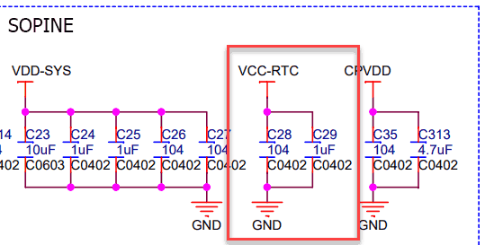
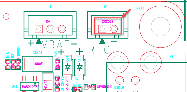
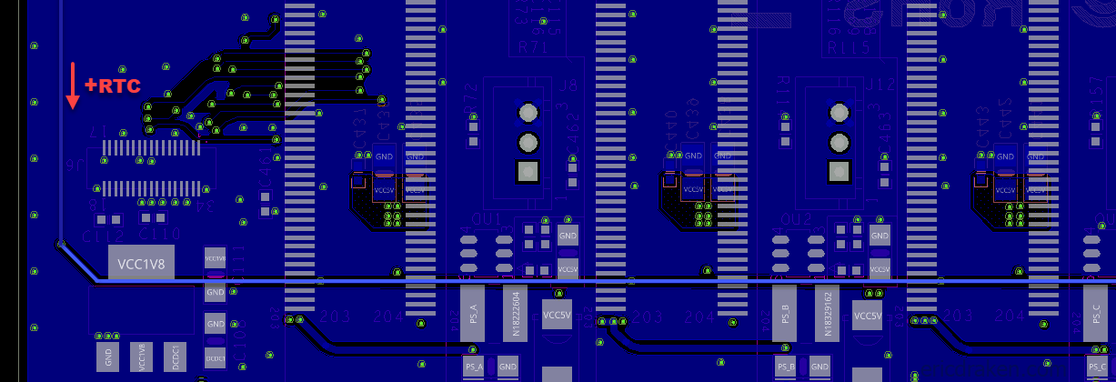
There is one other difference between the baseboard and clusterboard: powering the real-time clock (RTC). Let’s compare.
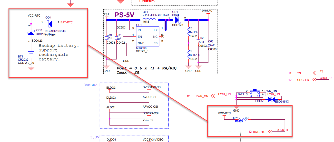
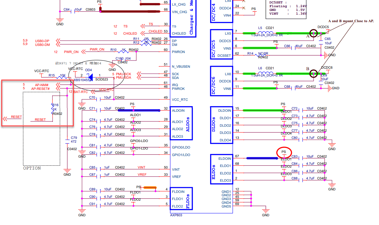
Did Pine64 revise the SOPINE module to sideline the 3.0V VCC-RTC from the power IC (PMIC) so only a physical battery can power the RTC? The schematics are in flux, so I’ll leave it to the experts to decide:
Just to be more convincing, here is the Pine64 LTS schematic:
Why should this matter? Isn’t the RTC optional and used to keep the date and time roughly accurate while the SoC is powered off? Let’s pull on this thread a bit since a powered RTC seemingly allows the SoC to reset.
From Allwinner,
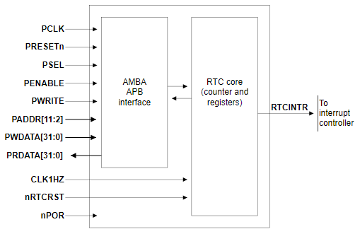
The real-time clock (RTC) is for calendar usage … The unit can be operated by the backup battery while the system power is off. … The alarm generates an alarm signal at a specified time in the power-off mode or normal operation mode. In normal operation mode, both the alarm interrupt and the power management wakeup are activated. (source)
It seems the RTC has an alarm that is capable of waking up power management. This could be what restarts the CPU. This could be the RTCINTR signal in the functional block diagram below from ARM.
Let’s ask some more questions.
If you are like me, you probably haven’t wondered why some SoC modules are prefixed with “R_”.
From my research,
The AR100, also called the CPUS or ARISC in SoC documentation is a coprocessor present in the A31 and newer sunxi SoCs. While the name “AR100” refers only to the OpenRISC CPU core, the processor is tightly integrated with other “RTC block” hardware. In general, any device whose name begins with “R_” is intended to be controlled by the AR100. This includes the R_PIO, R_PRCM, and several timers. (source)
From the A64 power docs, there is a VDD-CPUS pin to power the above. It’s safe to say that the A64 VCC-RTC pin powers only the RTC. So, no RTC power, no RTC alarm?
Holy smokes, the clusterboard resets!
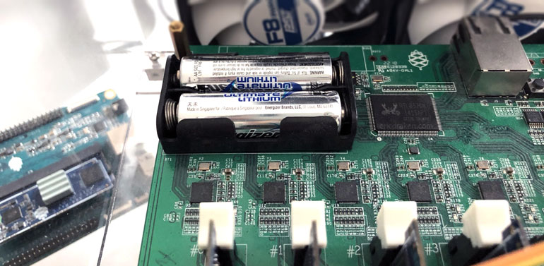
Baring any other discoveries, the current hypothesis is that the RTC needs power, and the only way to achieve that on the clusterboard is with batteries.
Let’s examine some RTC registers without and with external RTC (battery) power. Here is the test code.
1 2 3 4 5 6 7 8 9 10 11 12 13 14 15 | // bl31_main.c #define RTC_REG 0x01f00000 ... for (int i = 1; i <= 2000; i++) { INFO("%d ms: YMD: 0x%04x, HMS: 0x%04x, ALRM0_CNT: 0x%04x, ALRM0_CUR: 0x%04x, ALRM0_EN: 0x%01x, ALRM_CFG: 0x%04x\n", (i * 5), mmio_read_32(RTC_REG + 0x10), mmio_read_32(RTC_REG + 0x14), mmio_read_32(RTC_REG + 0x20), mmio_read_32(RTC_REG + 0x24), mmio_read_32(RTC_REG + 0x28), mmio_read_32(RTC_REG + 0x50) ); mdelay(5); } |
First, without batteries.
1 2 3 4 5 6 7 8 9 | INFO: 610 ms: YMD: 0x0101, HMS: 0x0001, ALRM0_CNT: 0x0000, ALRM0_CUR: 0x0000, ALRM0_EN: 0x0, ALRM_CFG: 0x0000 INFO: 650 ms: YMD: 0x0101, HMS: 0x0001, ALRM0_CNT: 0x0000, ALRM0_CUR: 0x0000, ALRM0_EN: 0x0, ALRM_CFG: 0x0000 INFO: 655 ms: YMD: 0x0101, HMS: 0x0001, ALRM0_CNT: 0x0000, ALRM0_CUR: 0x0000, ALRM0_EN: 0x0, ALRM_CFG: 0x0000 INFO: 660 ms: YMD: 0x0101, HMS: 0x0002, ALRM0_CNT: 0x0000, ALRM0_CUR: 0x0000, ALRM0_EN: 0x0, ALRM_CFG: 0x0000 INFO: 665 ms: YMD: 0x0101, HMS: 0x0002, ALRM0_CNT: 0x0000, ALRM0_CUR: 0x0000, ALRM0_EN: 0x0, ALRM_CFG: 0x0000 INFO: 670 ms: YMD: 0x0101, HMS: 0x0002, ALRM0_CNT: 0x0000, ALRM0_CUR: 0x0000, ALRM0_EN: 0x0, ALRM_CFG: 0x0000 INFO: 675 ms: YMD: 0x0101, HMS: 0x0002, ALRM0_CNT: 0x0000, ALRM0_CUR: 0x0000, ALRM0_EN: 0x0, ALRM_CFG: 0x0000 INFO: 680 ms: YMD: 0x0101, HMS: 0x0002, ALRM0_CNT: 0x0000, ALRM0_CUR: 0x0000, ALRM0_EN: 0x� -- no further output -- |
Now, with batteries to power the RTC. This is the same for the SOPINE baseboard.
1 2 3 4 5 6 7 8 9 | INFO: 395 ms: YMD: 0x0101, HMS: 0x0214, ALRM0_CNT: 0x0000, ALRM0_CUR: 0x0000, ALRM0_EN: 0x0, ALRM_CFG: 0x0000 INFO: 400 ms: YMD: 0x0101, HMS: 0x0214, ALRM0_CNT: 0x0000, ALRM0_CUR: 0x0000, ALRM0_EN: 0x0, ALRM_CFG: 0x0000 INFO: 405 ms: YMD: 0x0101, HMS: 0x0214, ALRM0_CNT: 0x0000, ALRM0_CUR: 0x0000, ALRM0_EN: 0x0, ALRM_CFG: 0x0000 INFO: 410 ms: YMD: 0x0101, HMS: 0x0214, ALRM0_CNT: 0x0000, ALRM0_CUR: 0x0000, ALRM0_EN: 0x0, ALRM_CFG: 0x0000 INFO: 415 ms: YMD: 0x0101, HMS: 0x0214, ALRM0_CNT: 0x0000, ALRM0_CUR: 0x0000, ALRM0_EN: 0x0, ALRM_CFG: 0x0000 INFO: 420 ms: YMD: 0x0101, HMS: 0x0214, ALRM0_CNT: 0x0000, ALRM0_CUR: 0x0000, ALRM0_EN: 0x0, ALRM_CFG: 0x0000 INFO: 425 ms: YMD: 0x0101, HMS: 0x0215, ALRM0_CNT: 0x0000, ALRM0_CUR: 0x0000, ALRM0_EN: 0x0, ALRM_CFG: 0x0000 INFO: 430 ms: YMD: 0x0101, HMS: 0x0215, ALRM0_CNT: 0x0000, ALRM0_C� -- a reset occurs -- |
The RTC seconds counter increments with and without batteries, as expected, but the alarm registers are all empty in both cases. I suspect the RTC is a red herring.
In several ARM SoC designs, the external non-maskable interrupt (AP-NMI#) pin and AP-RESET# pin are pulled high by the VCC-RTC. For example:
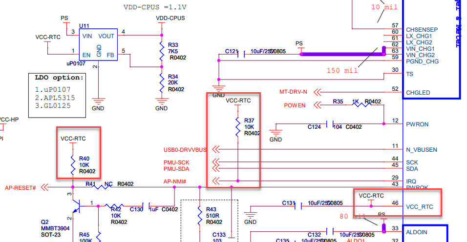
What is unique about the Pine64 designs is that the power IC (PMIC) does not feed the VCC-RTC line, whereas the majority of other SoC board designs have the dedicated, regulated PMIC VCC_RTC output feeding the RTC along with the battery via the VCC-RTC line as it is in the always-on power domain.
AXP803 power-management IC (PMIC) facts (ref):
- APX803’s PWROK pin is pulled up to RTCLDO (outputs to VCC_RTC) internally.
- RTCLDO is always on, even during power down or reset.
- RTCLDO is powered by IPSOUT and feeds from ACIN/VBUS or BAT.
- PWROK is tied to AP-RESET# on the A64 SoC.
- PWROK stands for Power-On Key, not “Power OK”.
- When PMIC is shut down, VCC_RTC will be shut off for two seconds and pulled to GND via 1kΩ.
- The IRQ pin needs a 10kΩ pull-high (usually to VCC-RTC) as it is NMOS open-drain.
Inferences:
- Without VCC-RTC to pull PMIC’s IRQ pin high, IRQ floats or is grounded. Without the battery does PMIC fail to signal an interrupt (AP-NMI#) to the SoC (possibly missing a wake-up signal)?
AP-RESET# is pulled high internally in the PMIC via RTCLDO, so the battery doesn’t affect this logic.
My new working hypothesis is that the NMI is never properly asserted without a battery on the clusterboard.
Interrupts are complex, so I’ll itemize some facts I’ve learned about the NMI pin.
SoC interrupt facts (ref):
- Allwinner sun50i SoCs (A31 and newer) have two interrupt controllers: GIC and R_INTC.
- GIC does not support wakeup and is inaccessible from the ARISC (power CPU).
- All IRQs that can be used to wake up the system are routed through R_INTC.
- All wake IRQs are enabled during suspend.
- R_INTC controls the NMI pin, the trigger, and mask for the NMI input pin.
- R_INTC provides the interrupt input for the ARISC coprocessor.
- R_INTC is in the always-on power domain.
- NMI pin is routed to the “IRQ 0” input on R_INTC.
- NMI trigger type is controlled by the NMI_CTRL_REG.
- SCP firmware = Crust = power management firmware.
- During suspend, the Crust will enable the interrupt input to the AR100.
- AR100 will treat any IRQ (subject to a mask) as a trigger to wake up.
- AR100 = CPUS = ARISC.
The NMI pin is the second-highest interrupt (IRQ), second to the RESET interrupt. When the SoC is reset or suspended, the NMI can easily trigger a wake-up and/or reinitialization of the BROM, CPUs, peripherals, and on. Additionally, the PMIC IRQ pin is asserted on thermal problems, rechargeable battery removal/insertion, power drop, and other programmable situations.
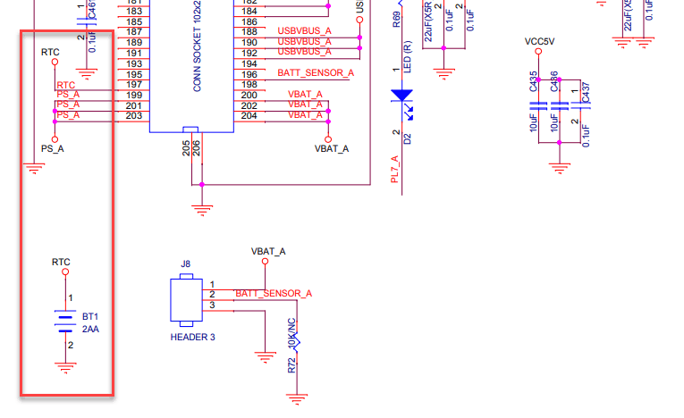
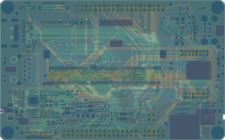
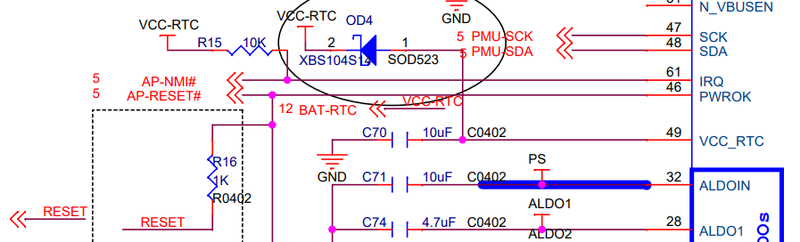
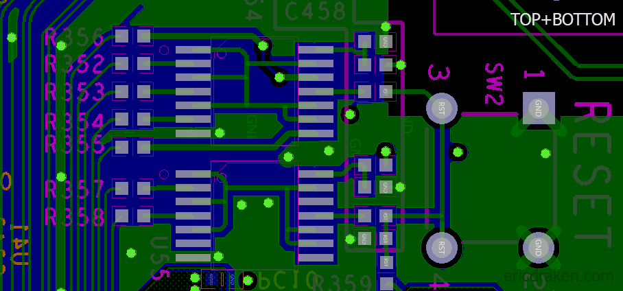
Here is the SOPINE baseboard schematic. Below is the PCB trace of the baseboard just for fun.
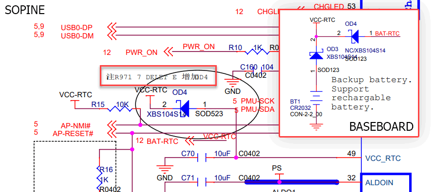
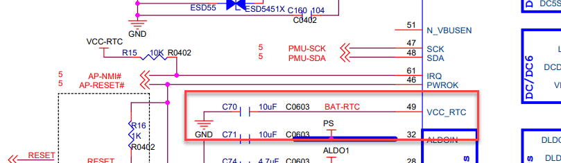
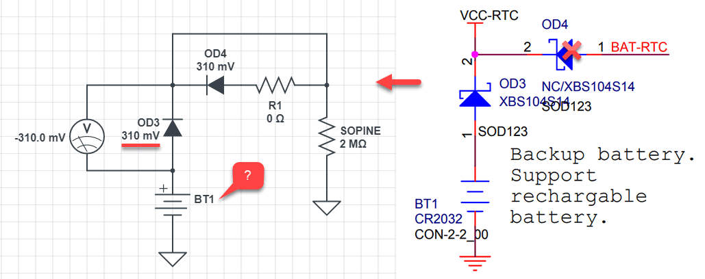
On my baseboard, diode OD4 is missing (which is good because VCC-RTC and BAT-RTC are shorted through a 0Ω resistor), so VCC-RTC is seemingly only powered by a battery. Let’s put a multimeter on VCC-RTC and see if it is powered.
Baseboard electrical measurements:
- SOPINE removed, power on, VCC-RTC is 0V.
- SOPINE removed, power off, VCC-RTC resistance is infinite.
- SOPINE inserted, power on, VCC-RTC is 2.78V.
- SOPINE inserted, power off, VCC-RTC resistance increases from ~1.5MΩ (settles on 3.25MΩ).
- SOPINE inserted, power on, 1kΩ series resister, VCC-RTC draws ~2.7mA.
- SOPINE inserted, power off, VCC-RTC capacitance is 0.96uF.
Clusterboard (v2.3) electrical measurements:
- SOPINEs removed, power on, VCC-RTC is 0V.
- SOPINEs removed, power off, VCC-RTC resistance is infinite.
- 7xSOPINE inserted, power on, VCC-RTC is 2.78V (across battery holder).
- 1xSOPINE inserted, power off, VCC-RTC resistance increases from ~700kΩ (settles on 3.26MΩ).
- 7xSOPINE inserted, power off, VCC-RTC resistance increases from ~140kΩ (settles on 240kΩ).
- 7xSOPINE inserted, power on, 1kΩ series resister, VCC-RTC draws ~2.7mA.
Clusterboard (v2.3) VCC-RTC capacitance measurements:
- 1xSOPINE inserted, power off, VCC-RTC non-convergent capacitance.
- 2xSOPINE inserted, power off, VCC-RTC capacitance is 1.9uF.
- 3xSOPINE inserted, power off, VCC-RTC capacitance is 3.1uF.
- 4xSOPINE inserted, power off, VCC-RTC capacitance is 4.7uF.
- 5xSOPINE inserted, power off, VCC-RTC capacitance is 6.6uF.
- 6xSOPINE inserted, power off, VCC-RTC capacitance is 8.9uF.
- 7xSOPINE inserted, power off, VCC-RTC non-convergent capacitance.
Clusterboard (v2.3) battery measurements:
- 2xAA new lithium batteries voltage is 3.6V.
- 2xAA, no SOPINEs inserted, power off, current draw is 0.00mA.
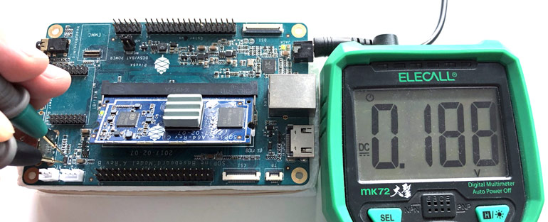
- 2xAA, 1xSOPINE inserted, power off, current draw is 0.07mA.
- 2xAA, 3xSOPINE inserted, power off, current draw is 0.19mA.
- 2xAA, 7xSOPINE inserted, power off, current draw is 0.45mA.
- 2xAA, 1xSOPINE inserted, power on, current draw is 0.43mA, resets.
- 2xAA, 2xSOPINE inserted, power on, current draw is 0.86mA, resets.
- 2xAA, 3xSOPINE inserted, power on, current draw is 1.29mA, resets.
- 2xAA, 7xSOPINE inserted, power on, current draw is 3.01mA, resets.
- 1xAA, 1xSOPINE inserted, power on, current draw is 160mA, no reset.
Observations:
- If VCC-RTC were connected to the PMIC’s VCC_RTC, then the 10uF (C70) would be in parallel, and the single SOPINE capacitance would be 11.1uF, not 1.1uF.
- A single SOPINE also doesn’t restart without battery power, same as seven SOPINES, in the clusterboard.
- A clusterboard SOPINE has a mathematical VCC-RTC resistance of 1.68MΩ.
- 2xAA lithium batteries with 7000mAh will last 1.77 years at 0.45mA RTC draw (power off).
- 2xAA lithium batteries with 7000mAh will last only 97 days at 3.01mA RTC draw (power on).
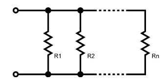
Given the measured 240kΩ VCC-RTC resistance across seven SOPINES, each one must have a 1.68MΩ resistance, but one was measured at 3.25MΩ. That is suspicious. Let’s measure the resistance across each SOPINE individually.
Settled VCC-RTC resistance per SOPINE:
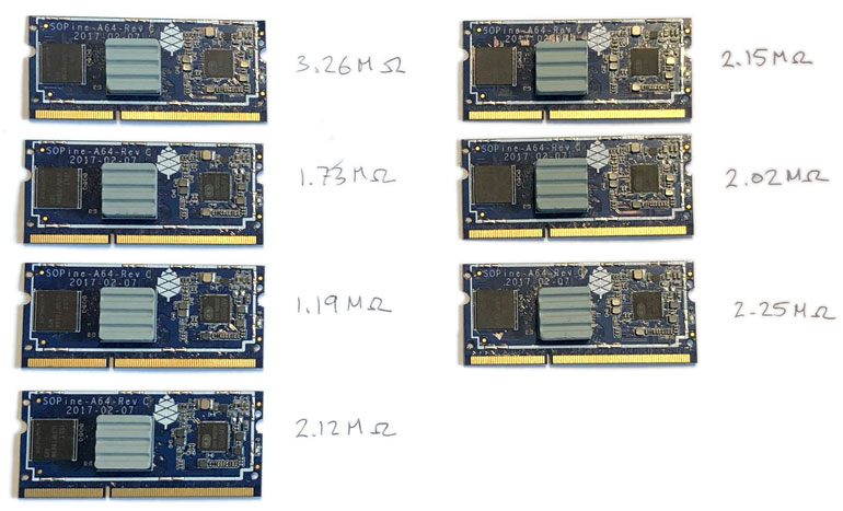
The parallel resistance is 278kΩ which is reasonably close to 240kΩ observed. We’ve learned the SOPINEs have different internal VCC-RTC resistances.
No. Both the 3.26MΩ SOPINE and the 1.19MΩ SOPINE fail to restart in the clusterboard, but both restart just fine in the baseboard. The problem likely isn’t related to a silicon defect.
No. Measured with an oscilloscope, the 32.768 kHz crystal (found just below the word “Designed” on the back of the SOPINE) outputs a perfect 32.768 kHz sine wave without batteries on the clusterboard. My hope was that somehow the xtal was unpowered so the RTC alarm wouldn’t activate.
It’s possible that power is supplied internally by the A64 SoC in lieu of no external, dedicated VCC-RTC from batteries. I’m not able to find detailed power diagrams for the A64 SoC, but from a design point of view, it makes sense that the VCC-RTC pin is not electrically isolated while the RTC is on main power.
Could there be a 0.22V drop on the VCC-RTC line through a diode from 3.0V from the PMIC? No. I’ve established that the PMIC isn’t powering the VCC-RTC line. Also, the Schottky diode that was “deleted” from the schematics has a 0.49V drop which is too high.
No. The clusterboard’s 5V@15A adapter outputs 5.16V, while the baseboard’s 5V@2A adapter outputs 5.36V. This doesn’t matter because the 5.15V is far away from the low-dropout voltage near the PMIC voltage of 3.0V for the RTC (which isn’t connected, anyway). I used an external PSU to reach 5.36V to power the clusterboard just to cover this unlikely possibility. External power can be excluded as a restart culprit.
If I can prevent a restart in the baseboard somehow, it may help understand how the wakeup process happens after a WDT reset.
However, when I cripple the device tree and the PMIC regulator initialization code in TF-A, baseboard WDT restarts still take place. I have not been able to prevent WDT restarts in the baseboard.
Crippled PMIC regulators in TF-A code:
1 2 3 4 5 6 7 8 9 10 11 12 13 14 15 16 17 18 19 20 21 22 23 24 25 26 27 28 29 | // axp803.c #include <drivers/allwinner/axp.h> const uint8_t axp_chip_id = AXP803_CHIP_ID; const char *const axp_compatible = "x-powers,axp803"; const struct axp_regulator axp_regulators[] = { {"dcdc1", 1600, 3400, 100, NA, 0x20, 0x10, 0}, {"dcdc5", 800, 1840, 10, 32, 0x24, 0x10, 4}, {"dcdc6", 600, 1520, 10, 50, 0x25, 0x10, 5}, // {"dldo1", 700, 3300, 100, NA, 0x15, 0x12, 3}, // disable // {"dldo2", 700, 4200, 100, 27, 0x16, 0x12, 4}, // disable // {"dldo3", 700, 3300, 100, NA, 0x17, 0x12, 5}, // disable // {"dldo4", 700, 3300, 100, NA, 0x18, 0x12, 6}, // disable // {"fldo1", 700, 1450, 50, NA, 0x1c, 0x13, 2}, // disable {} }; // Reference: //struct axp_regulator { // const char *dt_name; // uint16_t min_volt; // uint16_t max_volt; // uint16_t step; // unsigned char split; // unsigned char volt_reg; // unsigned char switch_reg; // unsigned char switch_bit; //}; |
Crippled device tree:
1 2 3 4 5 6 7 8 9 10 11 12 13 14 15 16 17 18 19 20 21 22 23 24 25 26 27 28 29 30 31 32 33 34 35 36 37 38 39 40 41 42 43 44 45 46 47 48 49 50 51 52 53 54 55 56 57 58 59 60 61 62 63 64 65 66 67 68 69 70 71 72 73 74 75 76 77 78 79 80 81 82 83 84 85 86 87 88 89 90 91 92 93 94 95 96 97 98 99 100 101 102 103 104 105 106 107 108 109 110 111 112 113 114 115 116 117 118 119 120 121 122 123 124 125 126 127 128 129 130 131 132 133 134 135 136 137 138 139 140 141 142 143 144 145 146 147 148 149 150 151 152 153 154 155 156 157 158 159 160 161 162 163 164 165 166 167 168 169 170 171 172 173 174 175 176 177 178 179 180 181 182 183 184 185 186 187 188 189 190 191 192 193 194 195 196 197 198 199 200 201 202 203 204 205 206 207 208 209 210 211 212 213 214 215 216 217 218 219 220 221 222 223 224 225 226 227 228 229 | /dts-v1/; / { model = "SOPINE with CRIPPLED baseboard"; #address-cells = < 0x01 >; #size-cells = < 0x01 >; aliases { mmc1 = "/soc/mmc@1c11000"; }; chosen { #address-cells = < 0x01 >; #size-cells = < 0x01 >; ranges; }; cpus { #address-cells = < 0x01 >; #size-cells = < 0x00 >; cpu@0 { compatible = "arm,cortex-a53"; device_type = "cpu"; reg = < 0x00 >; enable-method = "psci"; next-level-cache = < 0x01 >; clocks = < 0x02 0x15 >; clock-names = "cpu"; #cooling-cells = < 0x02 >; phandle = < 0x03 >; }; cpu@1 { status = "disabled"; phandle = < 0x04 >; }; cpu@2 { status = "disabled"; phandle = < 0x05 >; }; cpu@3 { status = "disabled"; phandle = < 0x06 >; }; l2-cache { compatible = "cache"; cache-level = < 0x02 >; phandle = < 0x01 >; }; }; osc24M_clk { #clock-cells = < 0x00 >; compatible = "fixed-clock"; clock-frequency = < 0x16e3600 >; clock-output-names = "osc24M"; phandle = < 0x07 >; }; osc32k_clk { status = "disabled"; phandle = < 0x08 >; }; pmu { status = "disabled"; }; soc { compatible = "simple-bus"; #address-cells = < 0x01 >; #size-cells = < 0x01 >; ranges; dma-controller@1c02000 { status = "disabled"; phandle = < 0x09 >; }; mmc@1c11000 { phandle = < 0x0a >; }; clock@1c20000 { status = "disabled"; phandle = < 0x02 >; }; serial@1c28000 { compatible = "snps,dw-apb-uart"; reg = < 0x1c28000 0x400 >; interrupts = < 0x00 0x00 0x04 >; reg-shift = < 0x02 >; reg-io-width = < 0x04 >; clocks = < 0x02 0x43 >; resets = < 0x02 0x2e >; phandle = < 0x0b >; }; interrupt-controller@1c81000 { status = "disabled"; phandle = < 0x0c >; }; dram-controller@1c62000 { status = "disabled"; phandle = < 0x0d >; }; rtc@1f00000 { status = "disabled"; phandle = < 0x0e >; }; interrupt-controller@1f00c00 { status = "disabled"; phandle = < 0x0f >; }; clock@1f01400 { status = "disabled"; phandle = < 0x10 >; }; }; binman { multiple-images; phandle = < 0x11 >; u-boot-sunxi-with-spl { filename = "u-boot-sunxi-with-spl.bin"; pad-byte = < 0xff >; blob { filename = "spl/sunxi-spl.bin"; }; fit { description = "Configuration to load ATF before U-Boot"; #address-cells = < 0x01 >; fit,fdt-list = "of-list"; images { uboot { description = "U-Boot (64-bit)"; type = "standalone"; os = "u-boot"; arch = "arm64"; compression = "none"; load = < 0x4a000000 >; u-boot-nodtb { }; }; atf { description = "ARM Trusted Firmware"; type = "firmware"; os = "arm-trusted-firmware"; arch = "arm64"; compression = "none"; load = < 0x44000 >; entry = < 0x44000 >; atf-bl31 { filename = "bl31.bin"; missing-msg = "atf-bl31-sunxi"; }; }; scp { description = "SCP firmware"; type = "firmware"; arch = "or1k"; compression = "none"; load = < 0x50000 >; scp { filename = "scp.bin"; missing-msg = "scp-sunxi"; }; }; @fdt-SEQ { description = "NAME"; type = "flat_dt"; compression = "none"; }; }; configurations { default = "config-1"; @config-SEQ { description = "NAME"; firmware = "atf"; loadables = "scp\0uboot"; fdt = "fdt-SEQ"; }; }; }; }; }; __symbols__ { cpu0 = "/cpus/cpu@0"; cpu1 = "/cpus/cpu@1"; cpu2 = "/cpus/cpu@2"; cpu3 = "/cpus/cpu@3"; L2 = "/cpus/l2-cache"; osc24M = "/osc24M_clk"; osc32k = "/osc32k_clk"; dma = "/soc/dma-controller@1c02000"; mmc2 = "/soc/mmc@1c11000"; ccu = "/soc/clock@1c20000"; uart0 = "/soc/serial@1c28000"; gic = "/soc/interrupt-controller@1c81000"; mbus = "/soc/dram-controller@1c62000"; rtc = "/soc/rtc@1f00000"; r_intc = "/soc/interrupt-controller@1f00c00"; r_ccu = "/soc/clock@1f01400"; binman = "/binman"; }; }; |
Even with disabled nodes and disabled interrupt controllers, WDT resets still take place on the baseboard.
1 2 3 4 5 6 7 8 9 10 11 12 13 14 | U-Boot SPL 2021.01 Armcube (Apr 03 2021 - 21:07:36 +0000) DRAM: 2048 MiB Trying to boot from MMC1 NOTICE: BL31: v2.4(debug):v2.4-dirty NOTICE: BL31: Built : 20:05:13, Apr 3 2021 NOTICE: BL31: Detected Allwinner A64/H64/R18 SoC (1689) NOTICE: BL31: Found U-Boot DTB at 0x407d2d0, model: SOPINE with CRIPPLED baseboard INFO: ARM GICv2 driver initialized <-- Disable this! INFO: Configuring SPC Controller INFO: PMIC: Probing AXP803 on RSB WARNING: PMIC: No PMIC DT node, skipping setup INFO: BL31: Platform setup done! INFO: BL31: Initializing runtime services ... |
No effect. Let’s disable that “ARM GICv2 driver” in TF-A code next.
1 2 3 4 5 6 7 8 9 10 11 12 13 | U-Boot SPL 2021.01 Armcube (Apr 03 2021 - 21:22:31 +0000) DRAM: 2048 MiB Trying to boot from MMC1 NOTICE: BL31: v2.4(debug):v2.4-dirty NOTICE: BL31: Built : 21:22:02, Apr 3 2021 NOTICE: BL31: Detected Allwinner A64/H64/R18 SoC (1689) NOTICE: BL31: Found U-Boot DTB at 0x407d2d0, model: SOPINE with CRIPPLED baseboard INFO: Configuring SPC Controller INFO: PMIC: Probing AXP803 on RSB WARNING: PMIC: No PMIC DT node, skipping setup INFO: BL31: Platform setup done! INFO: BL31: Initializing runtime services ... |
No effect. Let’s remove more TF-A code and see what happens. I’ve removed the security setup and even PMIC initialization.
1 2 3 4 5 6 7 8 9 10 | U-Boot SPL 2021.01 Armcube (Apr 03 2021 - 21:29:08 +0000) DRAM: 2048 MiB Trying to boot from MMC1 NOTICE: BL31: v2.4(debug):v2.4-dirty NOTICE: BL31: Built : 21:28:38, Apr 3 2021 NOTICE: BL31: Detected Allwinner A64/H64/R18 SoC (1689) NOTICE: BL31: Found U-Boot DTB at 0x407d2d0, model: SOPINE with CRIPPLED baseboard INFO: BL31: Platform setup done! INFO: BL31: Initializing runtime services ... |
No effect. Let’s obliterate all DTB loading code in the TF-A next.
1 2 3 4 5 6 7 8 9 10 | U-Boot SPL 2021.01 Armcube (Apr 03 2021 - 21:36:02 +0000) DRAM: 2048 MiB Trying to boot from MMC1 NOTICE: BL31: v2.4(debug):v2.4-dirty NOTICE: BL31: Built : 21:35:33, Apr 3 2021 NOTICE: BL31: Detected Allwinner A64/H64/R18 SoC (1689) NOTICE: BL31: No DTB found. INFO: BL31: Platform setup done! INFO: BL31: Initializing runtime services ... |
No effect. Let’s initiate a WDT reset as the very first thing TF-A does – a Hail Mary pass. Here is the code and results.
1 2 3 4 5 6 7 8 9 10 11 12 13 14 15 16 17 18 19 20 21 22 23 24 25 | // bl31/bl31_main.c void bl31_main(void) { NOTICE("BL31: %s\n", version_string); NOTICE("BL31: %s\n", build_message); INFO("** Let's try a reboot! **\n"); #define mmio_read_32(c) ({unsigned int __v = (*(volatile unsigned int *)(c)); __v; }) #define mmio_write_32(c, v) ((*(volatile unsigned int *)(c)) = (v)) #define TIMER_REG 0x01f01000 // Set the WDT timeout period in WDOG_MODE_REG mmio_write_32(TIMER_REG + 0xB8, (1 << 5)); // Set 7:4 to 0001 (...00010000) or 2s // Reset the WDT in WDOG_CTRL_REG mmio_write_32(TIMER_REG + 0xB0, (0xA57 << 1) | (1 << 0)); // Set 12:1 as 0xA57, and 0:0 to 1 // Set system reset function in WDOG_CFG_REG to 01 mmio_write_32(TIMER_REG + 0xB4, 0x1); // Enable watchdog in WDOG_MODE_REG mmio_write_32(TIMER_REG + 0xB8, mmio_read_32(TIMER_REG + 0xB8) | (1 << 0)); // Set 0:0 to 1 to enable WDT for(;;) {} } |
1 2 3 4 5 6 7 8 9 10 11 12 13 14 15 16 17 18 19 20 21 | U-Boot SPL 2021.01 Armcube (Apr 03 2021 - 21:41:49 +0000) DRAM: 2048 MiB Trying to boot from MMC1 NOTICE: BL31: v2.4(debug):v2.4-dirty NOTICE: BL31: Built : 21:41:20, Apr 3 2021 INFO: ** Let's try a reboot! ** U-Boot SPL 2021.01 Armcube (Apr 03 2021 - 21:41:49 +0000) DRAM: 2048 MiB Trying to boot from MMC1 NOTICE: BL31: v2.4(debug):v2.4-dirty NOTICE: BL31: Built : 21:41:20, Apr 3 2021 INFO: ** Let's try a reboot! ** U-Boot SPL 2021.01 Armcube (Apr 03 2021 - 21:41:49 +0000) DRAM: 2048 MiB Trying to boot from MMC1 NOTICE: BL31: v2.4(debug):v2.4-dirty NOTICE: BL31: Built : 21:41:20, Apr 3 2021 INFO: ** Let's try a reboot! ** ... |
No effect. Literally, the first action TF-A takes is to initiate a WDT reset, and it succeeds. Without DTB initialization, without GIC interrupts setup, and without any register writes at all except the WDT reset, a reset takes place. How can the baseboard WDT reset be disabled?
Another hardware difference between the clusterboard and baseboard is the presence of a small protection circuit to prevent the RX pin of UART0 from supplying power to the SoC while it is turned off.
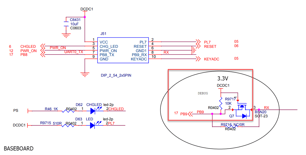
The clusterboard has no such circuit. As an experiment, I connected the clusterboard’s Z1 regulator’s input (DCDC1) to a 10kO resistor and then to the PB9_A pin of J4. No effect. No reset was observed.
Previously, I measured 2.78V across the baseboard’s battery jack in the diagram below.
This perplexed me earlier and sent me off in another direction because the un-batteried RTC voltage is the same in both the clusterboard and baseboard. According to the schematics, with no battery and hence no electrical connection to the OD3 Schottky diode, there should be 0V across the diode.
That is not 0V. Moreover, when I walk away and come back, the voltage across the diode changes.
Here is a circuit representation of the diode having an EMF across it.
What is really curious is that my body’s capacitance affects the voltage readings across the RTC. When my leg moves closer to the multimeter’s probe cables, the voltage changes.
Coming back to that 2.78V, the RTC voltage across the battery jack changes wildly depending on how far or close my body is to the baseboard like a theremin, or if I touch the positive line. Is the baseboard that sensitive?
Here is the same as above, but with a simple oscilloscope on the VCC-RTC battery line.
This waveform is interesting, actually.
With the oscilloscope, the DC-out of the wall adapter is a clean 5.3V with no latent ripple. You could level a picture frame by how flat the output is. This is surprising because the frequency of the waveform is approximately 60 Hz. Even though the voltage is clean, we shouldn’t discount the ground loop.
At first blush, it looks like a square wave is fed to a high-pass RC filter as explained in this StackExchange thread.
There is no 60 Hz PLL on the SOPINE. Any boost converters would operate outside human hearing well past 20 kHz. The two external clocks are 24 MHz and 32.7 kHz. The latter may cause a harmonic which appears to be around 60 Hz. Or, it may just be me and my human capacitive-antenna absorbing transient EM signals from the lights and mains cabling.
No. Operating on batteries in a minimal-EM environment results in the disappearance of the above waveform. As Dave shared with me, my body is likely operating as an antenna for surrounding mains EM with the wall adapter facilitating the unwanted circuit.
On batteries through a 5V USB battery, we can see 2.78V is consistently observed without stray, human capacitance.
As an aside, just measuring the waveform across the RTC battery terminals with an oscilloscope drops the voltage reading from 2.78V to 0.3V. This oscilloscope has capacitance and resistance, and it looks like it is preventing an RC circuit from charging a baseboard capacitor. When the scope is removed, a baseboard capacitor slowly charges as seen below.
Let’s explore something else and come back to that diode voltage.
This time on 5V batteries, there is no OD3 diode voltage anymore. It is gone. It was an artifact of stray capacitance and ambient EM radiation passing through a rectifier.
We can, however, bypass the diode and see how the VCC-RTC line behaves. When I short the OD3 diode, the oscilloscope no longer interferes with the VCC-RTC voltage and we can see about 2.78V.
The clusterboard has no such rectifier and shows a nominal scope output across VCC-RTC.
Is the conclusion that the VCC-RTC is also unpowered on the baseboard, there is no leak or PCB error, yet an externally-powered RTC is not what wakes up the baseboard?
Unable to give up, let’s turn to the powered microscope and physically map the VCC-RTC line on the SOPINE module.
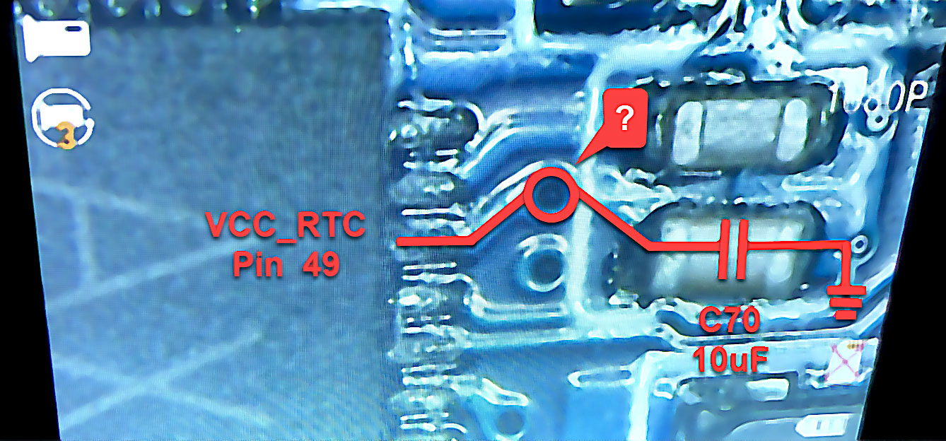
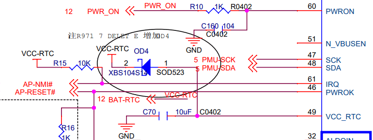
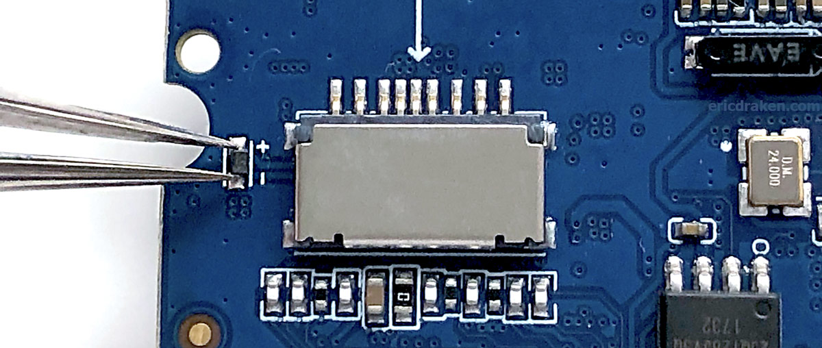
Hello. Where is this little hole taking the electron flow? There should be no other components on the PMIC’s VCC_RTC line beside that 10uF capacitor. There was an OD4 diode, but it is deleted from the schematics.
Let’s see where this hole goes.

The diode exists. In fact, it is the only Schottky diode in the schematic. It is stamped “SS”, short for “SS14”, which is an AliExpress-found equivalent for the XBS104S14 the schematic called (calls?) for. It’s not supposed to exist. Could this be powering the VCC-RTC line? Let’s see.
The VCC-RTC line is powered by the PMIC. In fact, placing the probe right on pin 49 of the PMIC (VCC_RTC) shows 3.00V. Placing the probe on the diode also shows 3.00V on one side and 2.80V on the other side.
Wait. The voltage drop across the diode is 0.2V? That doesn’t match the typical forward voltage drop of 0.49V in the specs. It turns out in the graphs, under a very low current the forward voltage drop can be around 0.2V.
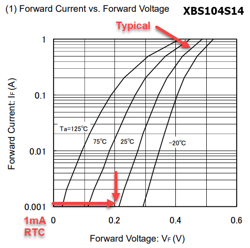
This 2.80V is remarkably close to the 2.78V measured across the battery terminals, enough so that I am satisfied.
The real-time clock (RTC) is powered and running. Then why does only an RTC battery enable a clusterboard SOPINE wakeup, but one is unnecessary in the baseboard? We are seemingly back at square one.
A voltmeter and an oscilloscope with a microsecond range (by default) show an instantaneous 2.78V. Let’s make the scope more sensitive and stretch the time range to see if there are any dropouts.
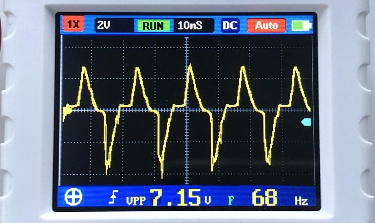
Yes! The clusterboard experiences small voltage dropouts when observed over a period of several seconds. From the image above, the RTC voltage drops from 2.78V to about 2V briefly. Here is a video of this phenomenon.
These voltage dropouts only happen when on 5V battery power. When the clusterboard is powered by the 15A brick adapter, no dropouts occur. I suspect a clusterboard with a single SOPINE module draws more than 1A – the limit of my USB batteries.
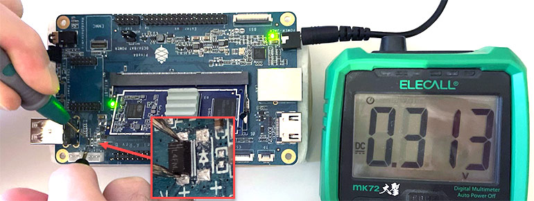
Why not give the clusterboard VCC-RTC the full 3.00V without 2xAA batteries? Shot in the dark, with only one SOPINE on the clusterboard for obvious safety, let’s short the OD4 diode on the SOPINE module (to reclaim that 0.2V drop) and observe the UART line to see what the SoC does if anything.
The SOPINE in the clusterboard sometimes resets! Without 2xAA batteries (and yes without shorting VCC to GND), a reset is triggered, but only sometimes.
Could it be possible there is just not enough current reaching the RTC? When on USB 5V batteries, the VCC-RTC did experience voltage dropouts seemingly around when the RTL8211E chips were blinking. Raising the VCC-RTC line to 3.00V may have taken the line right on the cusp of supplying sufficient current to fully operate the RTC.
The AXP803 PMIC spec shows the RTCLDO (VCC_RTC) supplies 60mA typical. There is a 10kΩ pull-up resistor drawing 2.8V/10kΩ or 0.28mA ≪ 60 mA, so current isn’t lost there. How about that PWROK pin? We learned earlier it is tied to RTCLDO. Let’s see where its current goes.
The worst-case current seems to be if RESET is tied to GND which becomes 3.0V/1kΩ or 3mA ≪ 60 mA. However, there is a huge difference between the baseboard and the clusterboard: the baseboard has no reset mechanism, while the clusterboard has NOT-gates which constantly draw current.
How much current? Let’s turn to the 74LVT04 logic IC specs.
The -32mA stands out for the high output which is the default state. However, two NOT-gates are used per SOPINE, so I’m unsure how to calculate the negative current draw on RESET. It’s possible there is enough EMF to draw a higher current on the RESET line through the PWROK pin and finally through the VCC_RTC which meets or exceeds the 60mA (and 100mA max) of the PMIC.
After two days of effort with Multisim and OrCAD, the experience is too painful. The NXP line of BiCMOS 74LVTxx components is not found in either simulation suite, and efforts to download and/or import the model files from 1999 have left me shaking my head.
I’m hoping my StackExchange question can help. I got close with OrCAD, but not close enough. The problem with using digital parts in Multisim is the internal current and resistances are not simulated, which is what we crucially need.
In the meantime, let’s resist the temptation to slice this delicious wire separating the SOPINE RTC from the clusterboard, yet in which doing so would definitely answer the question of whether the non-reset culprit is ironically the reset distributor.
StackExchange came through. We can now simulate the electrical characteristics of the 74LVT04 hex inverter.
However, when I attempt to recreate the SOPINE schematic around the RTCLDO, the clusterboard electrical values don’t match real measurements, plus I see high-frequency ringing and pulses of high voltage.
When I read the AXP803 manual carefully, I realize the PWROK is a push-pull line pulling to VCC_RTC internally. What is this? Research shows it is a GPIO line flanked by two transistors (MOSFETs?), one connected to GND, and the other to VCC_RTC. Let’s try to simulate that with ideal MOSFETs.
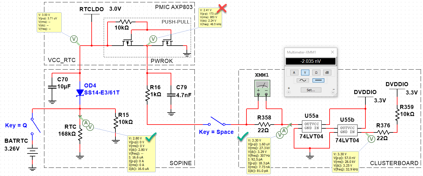
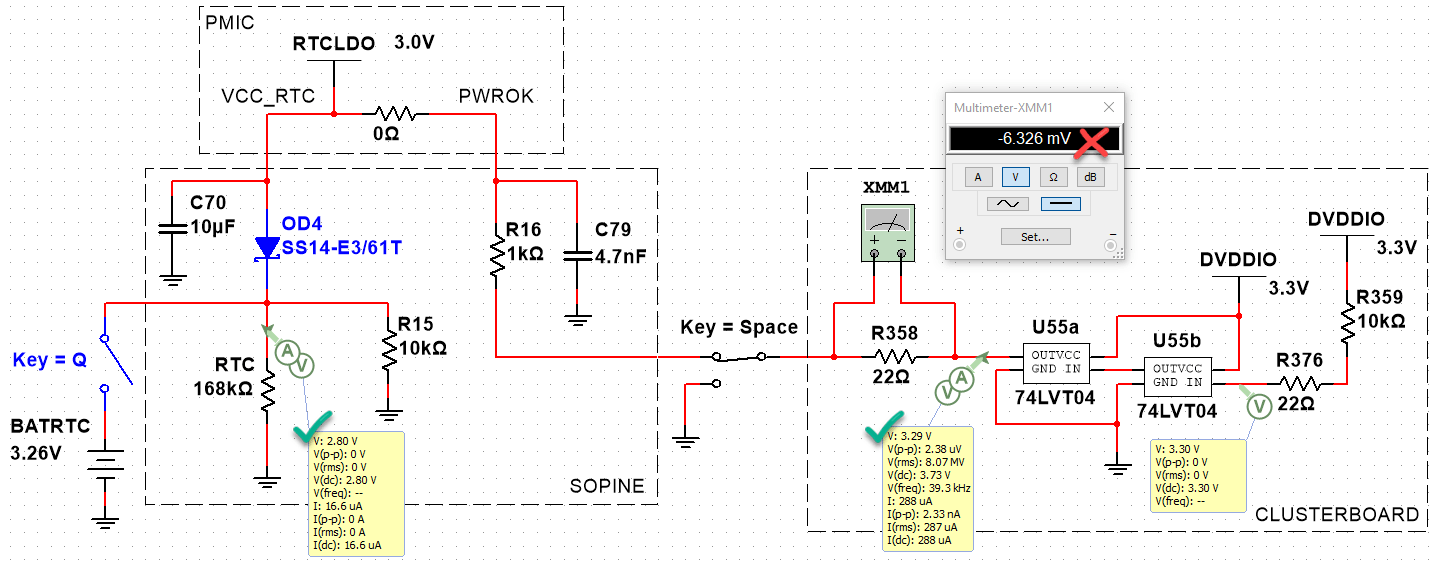
By putting a probe between R16 and C79 on the SOPINE, we can measure the PWROK line voltage. There is a difference between the baseboard and the clusterboard:
- Baseboard PWROK: 3.00V
- Clusterboard PWROK: 3.24V
- Clusterboard R358: -2mV
- Clusterboard RESET_A, SOPINE inserted: 3.29V
- Clusterboard RESET_A, no SOPINE: 3.29V

Even though the push-pull MOSFETs are not correct, we can simulate the 74LVT04 feeding 3.3V into the PWROK line which is supposed to be a max of 3.00V. This is as far as we can simulate, however. We can see how complex this is becoming, and how many unknown components there are to guess.
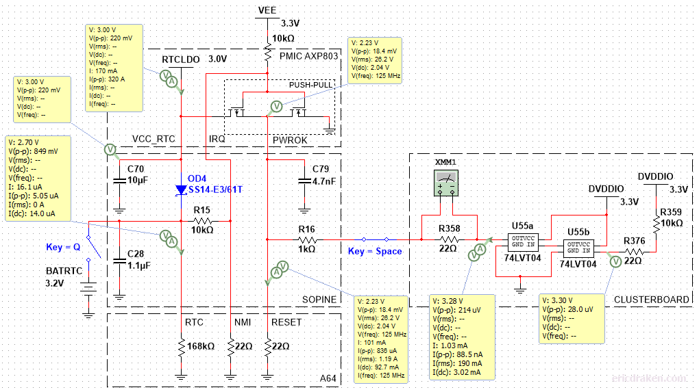
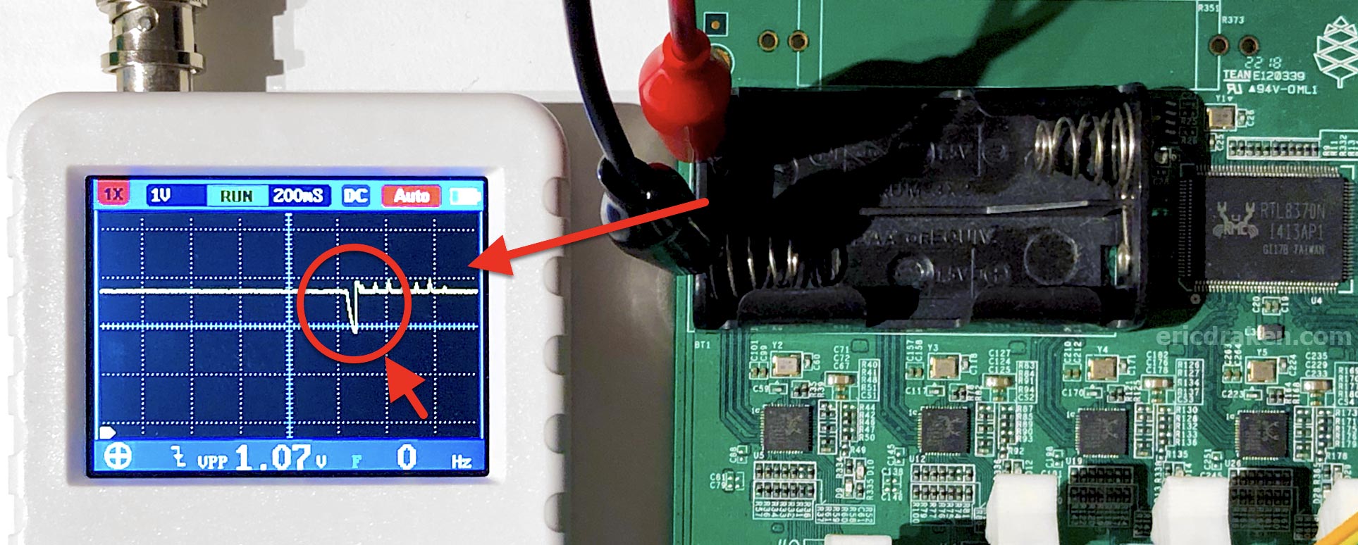
Simulations aren’t panning out. We don’t have any information on the design of the push-pull and how it reacts to back-EMF from the 74LVT04. We just know 3.3V of back-EMF prevents a WDT reset. Let’s try something else. Now that we know how to measure the PWROK line (and RESET input), let’s graph the voltage around resets.
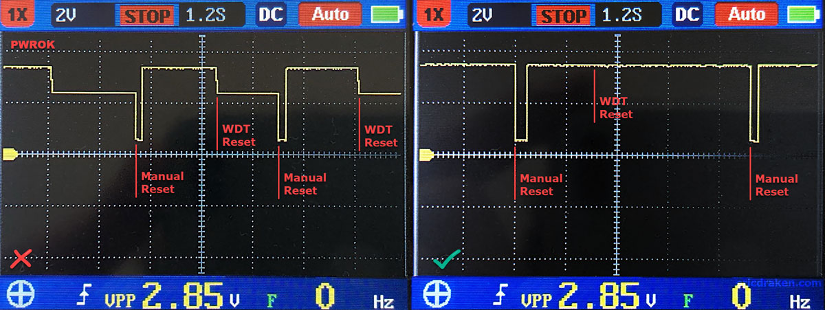
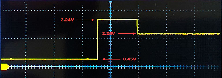
This is a wonderful discovery. It means we are on the right track. The left waveform is self-explanatory. The right waveform is more interesting. Here are the observations (15A power, one SOPINE, clusterboard):
Left PWROK waveform:
- No RTC battery, WDT reset fires after 2s.
Right PWROK waveform:
- No RTC battery, no WDT reset.
- RTC battery, no WDT reset.
- RTC battery, WDT reset fires after 2s.
The right waveform is identical for the above three observations as well. Only the left waveform is unusual for normal operations.
Turning to the electrical guide of the A64, we see that VCC-IO can range from 3.0V to 3.6V.
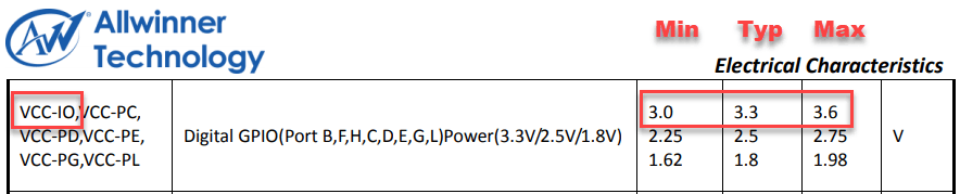
In the SOPINE schematic, VCC-IO is supplied by DCDC1 from the PMIC, which is regulated at 3.3V. Then, on page 34 of the datasheet, we see the following table.
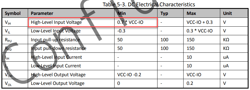
Then, 0.7 * 3.3V = 2.31V. Thus, the minimum threshold for a HIGH signal (no reset) on the A64 RESET# line from PWROK is 2.31V, yet PWROK drops to 2.25V – still HIGH?
But is it LOW? The upper threshold for a LOW signal is 0.3 * 3.3V = 0.99V. What does inverting-logic RESET do when the signal is between HIGH and LOW? The datasheet indicates the line is not pulled up or down. Normally the region between logic thresholds is undefined, but RESET is inverted. Here is a possible logic inverter with a single Darlington pair (I chose values for saturation at 2.3V to show the effect clearly).
Among friends, let’s state the supposition that under 2.3V a RESET will occur until we know more. Now we can move on to how to solve this problem without 2xAA batteries by preventing the voltage drop at all.
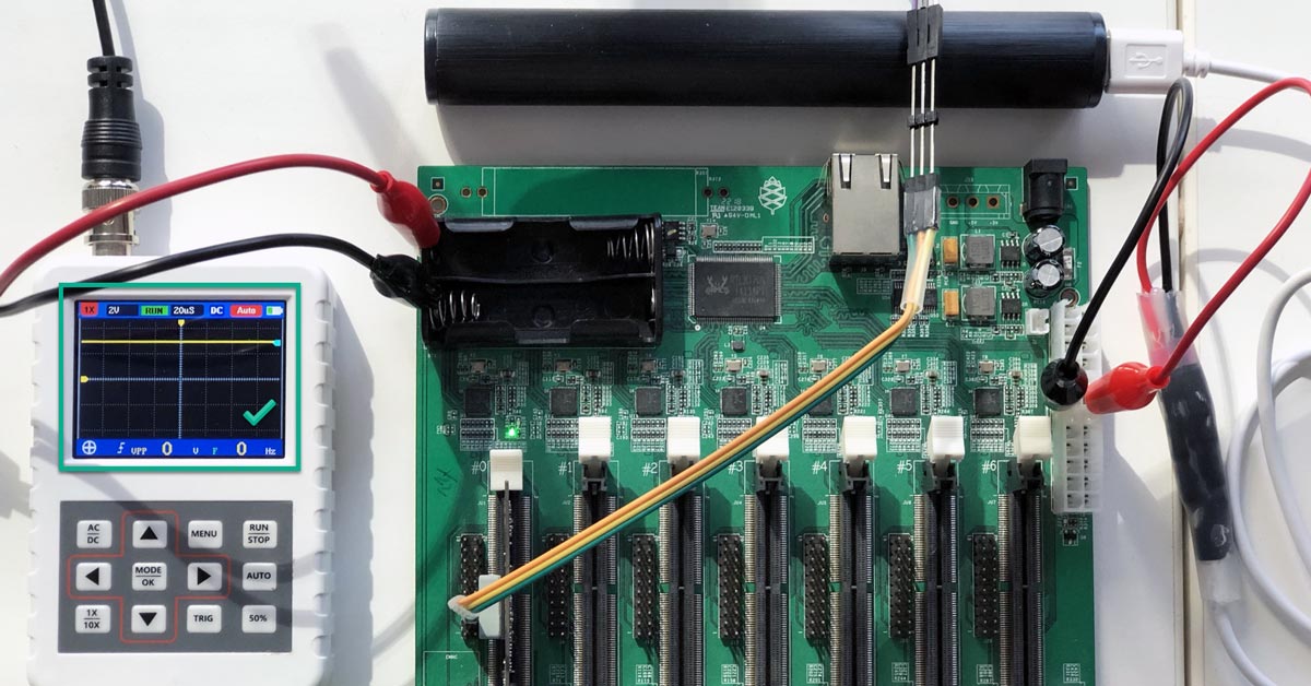
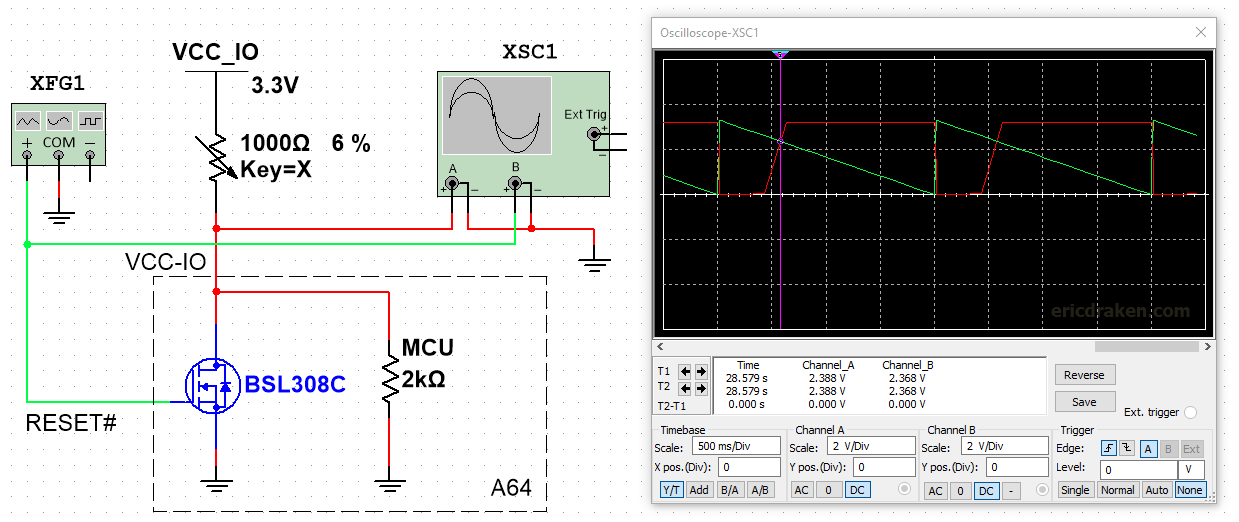
How to solve this back-EMF from the clusterboard reset distributor without resorting to SMD re-soldering (or batteries)? Below is a fun animation I made while I wait for some custom testing hardware to arrive.
The positive line from the RTC battery runs directly into the seven SOPINES through the 204-pin DDR3 SODIMM connectors. Those run directly into the VCC-RTC pins on the A64 ICs. The PMIC VCC_RTC out is protected by the Schottky diode per SOPINE. However, the NMI-IRQ line is susceptible to the battery’s EMF, and the battery experiences reverse voltage from the NMI-IRQ line. A Schottky diode with, say, a 0.2V drop on this line will help the battery (until it drops below 2.8V!) but doesn’t address the reset problem.
Until we understand how back-EMF on PWROK prevents a reset and how a battery on IRQ allows it again, let’s try to force 3V on the RTC line from some other source on the clusterboard to simulate a connected battery.
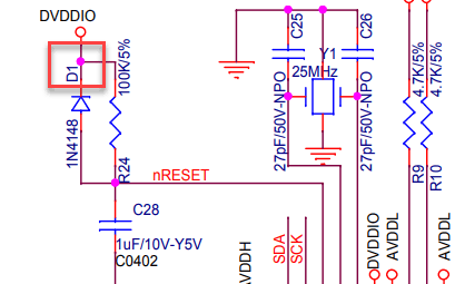
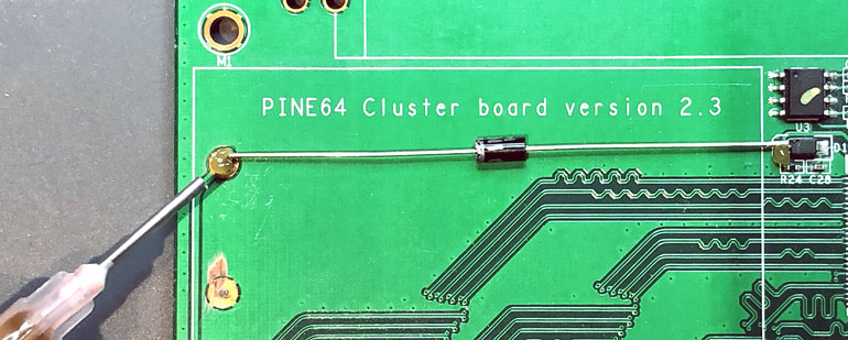
The DVDDIO (AVDDH) line on the clusterboard supplies 3.3V and runs through a middle PCB layer on the clusterboard. Let’s see if we can place a common diode between it and the +RTC battery terminal. But, where does a DVDDIO pin come up for air, and which diode will maintain 3.0V or more?
The cathode (-) of diode D1 is a perfect tap: it has 3.3V, is regulated by the clusterboard, is large enough to solder with conventional tools, and is right beside the battery holder. You read that right: the cathode (minus side) is the target.
Diodes are neat. They behave differently under different voltages and loads, however. We need at least 3.0V on RTC with one SOPINE and seven SOPINEs. Let’s simulate how a handful of diodes behave under different loads.
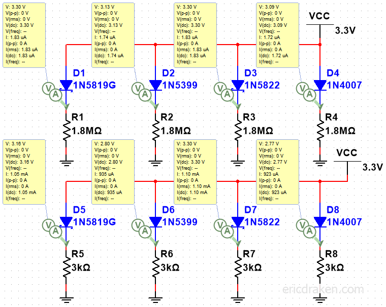
Here, a couple of barrier diodes stand out: 1N5819 (1A) and 1N5822 (3A). These are ones I happen to have.
WDT reset works. Hardware reset works. Normal operation works. How satisfying.
Solution & Discussion
The reset distributor on the clusterboard would be better served with normally-floating outputs (not active high) and pulled low when in reset mode (like a momentary switch).
Who knew that some back-EMF from a system we take for granted would interfere with the little-known circuitry of the PMIC that cannot even be simulated because it is reactive?
There is no bypass or hack that can be applied to the clusterboard v2.3 reset distributor itself, so countering the 74LVT04 back-EMF with 3.3V on the RTC battery line, and possibly adding a diode between the battery holder positive terminal and the +RTC line to protect the battery, is a reset solution for under 50 cents.
Solution Details
You can probably run a diode on the outside of the battery holder.
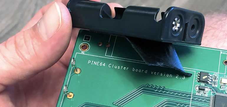
Personally, I’d like to remove the battery holder and affix the barrier diode. The holder is held with a weak glue pad which can gently be pried up by hand, but be gentle with the copper pads. If we manage to keep our copper pads intact, we end up with the following fix.
Remove the Battery Holder Easily
An effective way to remove the battery holder without a soldering iron is to use an Exacto knife on the tiny metal flaps on the battery holder posts.
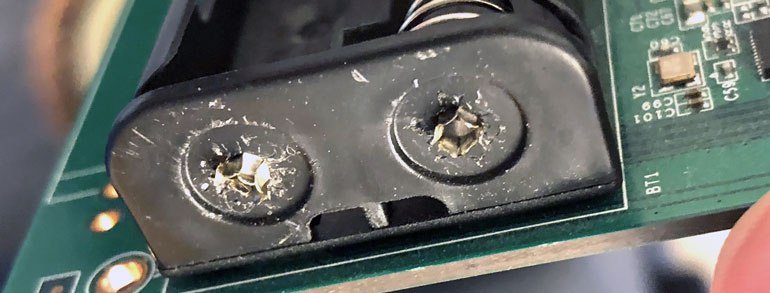
With a Jeweler’s screwdriver, push the middle of both terminals so the metal pieces fall through and off.
We will be left with a battery holder that is easy to pull off, only held by sticky tape, because the PCB posts are no longer attached to the battery holder.
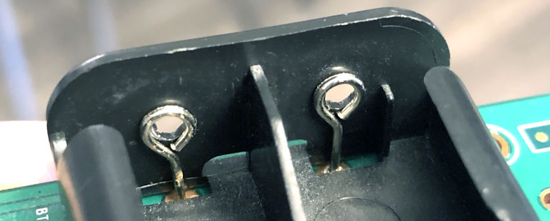
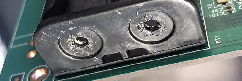
Simply lift up the battery holder from the far end without tools.
With clippers or a Dremel, we can cut the battery posts to mere nubs. Be careful not to Dremel the PCB mask layer (green layer).
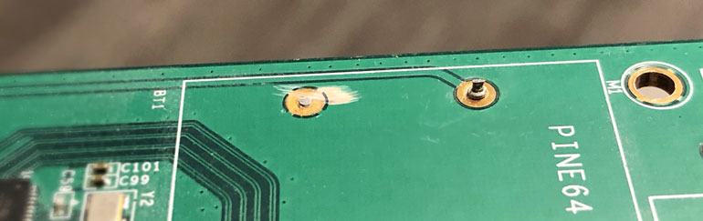
Solder the Low-Forward-Voltage Schottky Diode
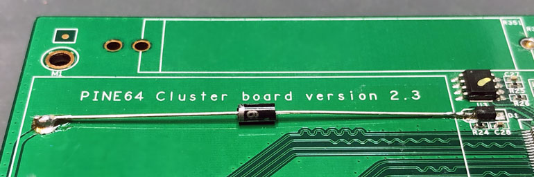
Simply place the 1N5819 diode with the silver band facing the +RTC terminal on the clusterboard and add some flux before soldering.
One suggestion is to hold the diode down with a clip before soldering.
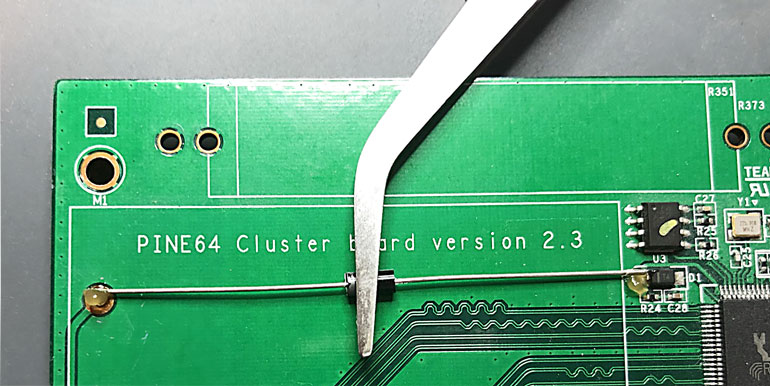
Finally, tin the soldering iron, and within 2~3 seconds per terminal, apply solder to the D1 diode and then the +RTC solder pad. Clean the flux with a saponify cleaner, or isopropyl alcohol with a Q-tip works well.
The end result should look something like this.